


Available from:
Aliexpress.com
Install method:
USB to Serial
| GPIO # | Component |
|---|---|
| GPIO00 | None |
| GPIO01 | None |
| GPIO02 | ALux IrSel |
| GPIO03 | None |
| GPIO04 | None |
| GPIO05 | None |
| GPIO09 | None |
| GPIO10 | None |
| GPIO12 | PWM 1 |
| GPIO13 | PWM 2 |
| GPIO14 | None |
| GPIO15 | None |
| GPIO16 | None |
| GPIO17 | None |
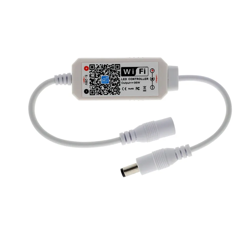
{"NAME":"MagicHome RF","GPIO":[0,0,3168,0,0,0,0,0,416,417,0,0,0,0],"FLAG":0,"BASE":38}Snap the case open by using a prying tool on the top side, it will click back in place.
In the rear side of the PCB there are all the contacts you need for flashing the device (GND, 3V3, TX, RX and IO0)
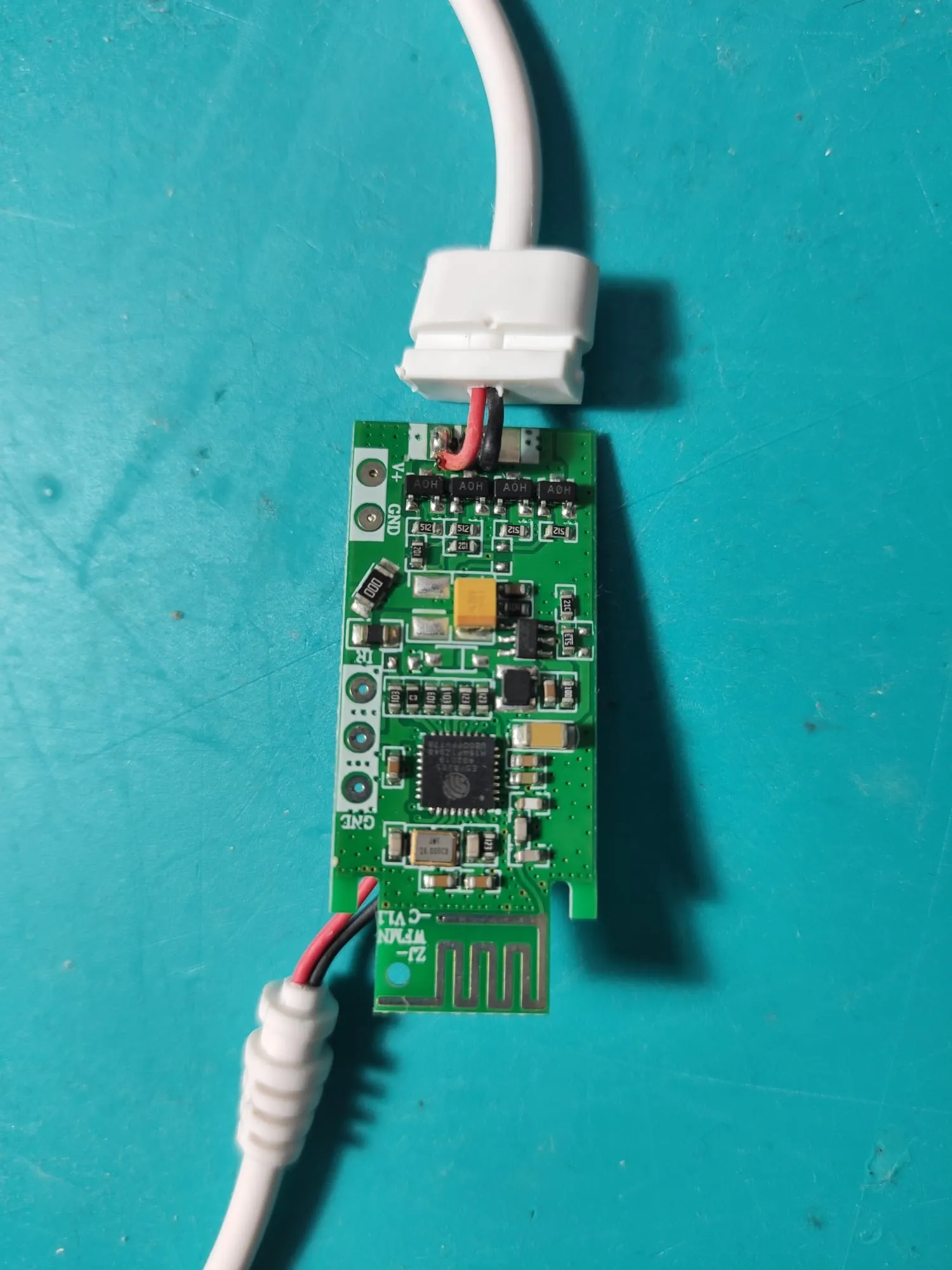
There are 4 output transistors connected in 2 couples (next to each other).
The rear of the PCB has contacts for CW WW and V+. The front of the PCB has the output contacts (black and red cables, and an empty one). The red output is connected to the rear V+ contact, and to the board power input labelled as V+ as well. The WW contact in the rear is shorted to the black output contact. The CW contact in the read is shorted to the unused unlabelled contact in the front, next to the output connector.
This board is designed to drive 2 channels, warm/cool white string, although we can use it to drive 2 different LED strings. To enable that functionality we need to perform 2 changes:
1: Change the placement of the resistor according to the provided image. It’s a resistor so don’t worry about polarity. 2: Solder another connector in the rear side of the PCB: Positive to V+ and negative to CW. 3: Make a hole for the new connector in the case and the lid. I used a soldering iron and knife to do so.