Available from:
Amazon.com
Install method:
USB to Serial
| GPIO # | Component |
|---|---|
| GPIO00 | Button 1 |
| GPIO01 | None |
| GPIO02 | None |
| GPIO03 | None |
| GPIO04 | None |
| GPIO05 | None |
| GPIO09 | None |
| GPIO10 | None |
| GPIO12 | Relay 1 |
| GPIO13 | Led_i 1 |
| GPIO14 | None |
| GPIO15 | None |
| GPIO16 | None |
| GPIO17 | None |
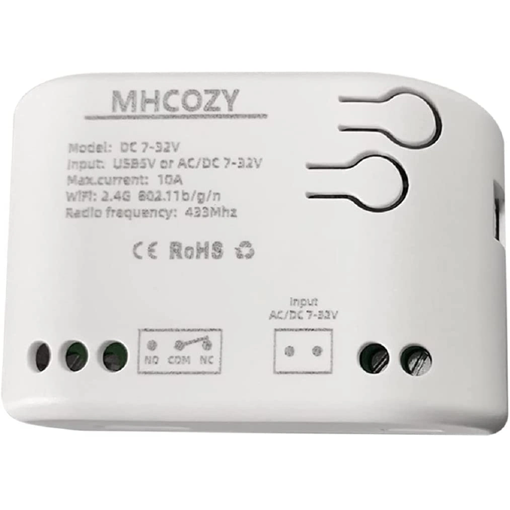
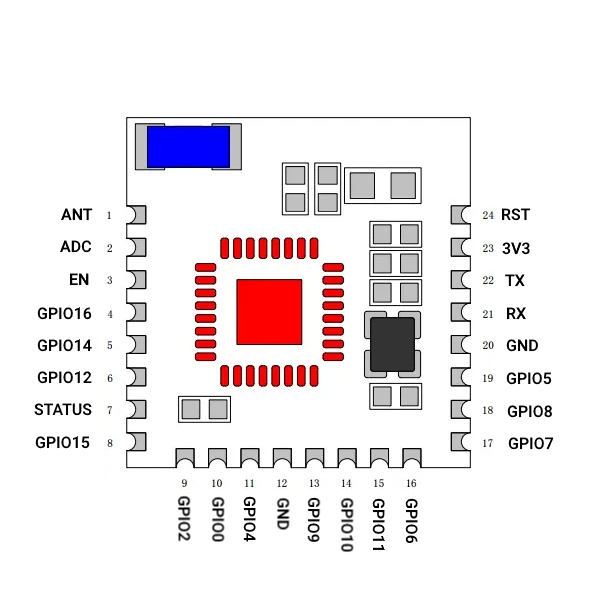
{"NAME":"MHCOZY RF 1CH","GPIO":[32,0,0,0,0,0,0,0,224,320,0,0,0,0],"FLAG":0,"BASE":18}Power by 5V USB mini, or 7-32V AC/DC (tested with USB, and 24VAC [27VAC actual] 40VA doorbell transformer). WiFi module is PSF-B01 itead ESP8285. Board does not have pin headers, etc., so must be flashed by either directly soldering to the PSF module, or using a jig such as:
https://www.thingiverse.com/thing:4841261 or https://www.thingiverse.com/thing:4772985
On board button connects GPIO0 to Ground, and can be used to enter flashing mode. Plastic case does not contain screws, but does have two clips per long side. Gentle use of a prying tool or small flat head screw driver is recommended for disassembly.
Pinout
 .
.


