


Available from:
Ledbe.com
Manufacturer:
Miboxer.com
Install method:
Replace module
| GPIO # | Component |
|---|---|
| GPIO00 | None |
| GPIO01 | None |
| GPIO02 | None |
| GPIO03 | None |
| GPIO04 | None |
| GPIO05 | None |
| GPIO06 | None |
| GPIO07 | None |
| GPIO08 | None |
| GPIO09 | None |
| GPIO10 | None |
| GPIO12 | None |
| GPIO13 | None |
| GPIO18 | None |
| GPIO19 | None |
| GPIO20 | Tuya Rx |
| GPIO21 | Tuya Tx |
{"NAME":"Miboxer-TRI-C1WR","GPIO":[0,0,0,0,0,0,0,0,0,0,0,0,0,0,0,0,0,0,0,0,2304,2272],"FLAG":0,"BASE":54,"CMND":"SO97 1 | TuyaMCU 11,20 | TuyaMCU 98,21 | TuyaMCU 21,22 | TuyaMCU 12,102 | TuyaMCU 22,103 | DimmerRange 10,1000"}
Identified with MCU Product ID: {"p":"ws3odtueeha5yjln","v":"1.0.1","m":0}.
Please read TuyaMCU article to understand the terminology and configuration process.
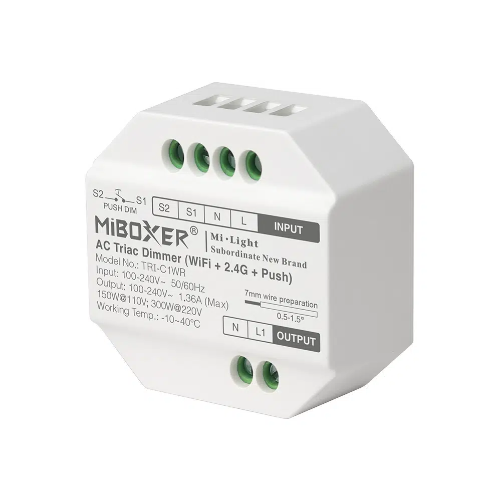
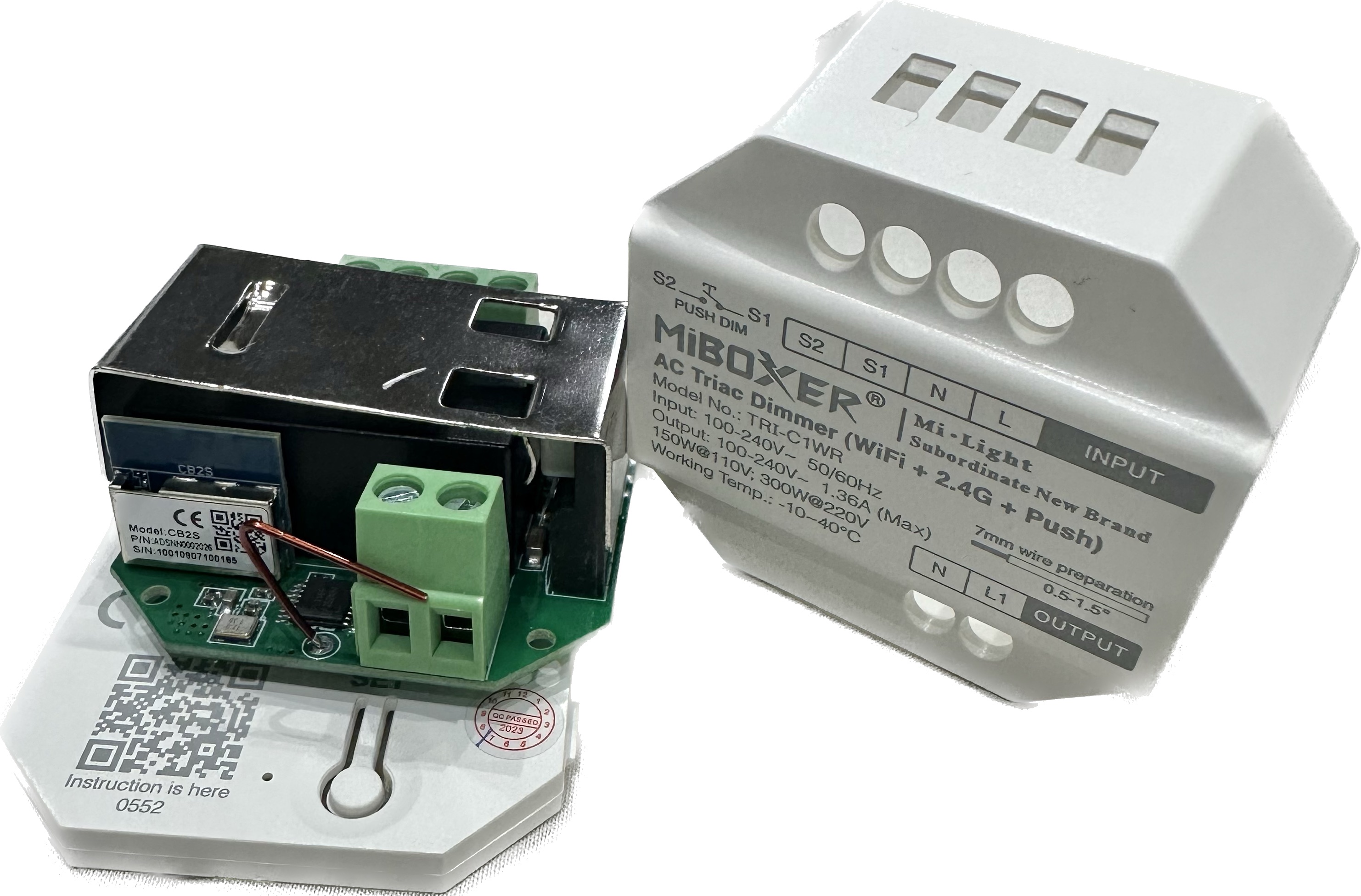
Hardware
The Miboxer TRI-C1WR Dimmer Module uses the UART to communicate with Tuya MCU. This Dimmer Module comes with a CB2S chip and requires replacement in order to be used with Tasmota.
The TuyaMCU on board requires the following settings.
Backlog TuyaMCU 11,20; TuyaMCU 98,21; TuyaMCU 21,22; TuyaMCU 12,102; TuyaMCU 22,103; TuyaMCU 13,104; DimmerRange 10,1000
Functions
| dpID | Function | Datatype | Additional Comments |
|---|---|---|---|
| 20 | Dimmer Switch | Switch | |
| 21 | Work Mode? | Enum | 0 = Mode 1, 1 = Mode 2, 2 = Mode 3, Range 0 .. 4? |
| 22 | Dimmer Level | Integer | Value Range: 0 .. 1000 |
| 103 | Min Brightness | Integer | Value Range: 0 .. 255 |
| 102 | Breaker Mode | Switch | |
| 104 | TRIAC Mode Leading Edge? | Switch | |
| 105 | undocumented? | Enum | 0 = Mode 1, 1 = Mode 2, 2 = Mode 3, Range 0 .. 4? |
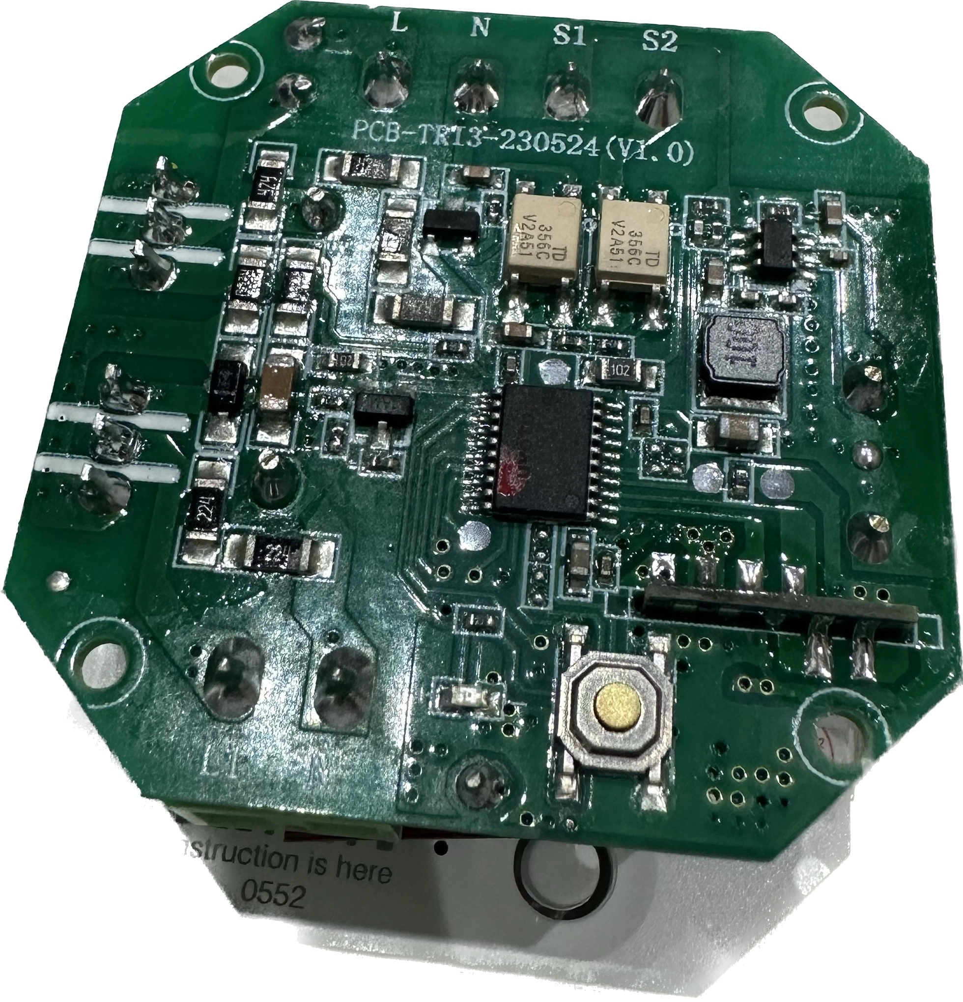
Serial Flashing
Please see the Hardware Preparation page for general instructions.
Flash using Tasmota Web installer and select ESP32-C3 option.
To put ESP32-C3 in flash mode EN needs to be pulled high and GPIO9 need to be pulled low. May take a 2-3 attempts, but just disconnect and reconnect 3V3 while keeping GPIO9 pulled low and click the retry button again until it works.
Any CP2102 or CH340 based USB to serial adapter is fine.
| ESP32 Pin | USB Serial Pin | Comments |
|---|---|---|
| 3V3 | 3V3 | Connect to dedicated 3V3 1A power supply if encountering brown out |
| G | GND | |
| IO9 | Ground | Round contact pad on back of board, pull low BEFORE attaching 3V3 |
| IO8 | 3V3 | Could not find this pin, but it didn’t seem to be required |
| TX | RX | |
| RX | TX | |
| EN | 3V3 | Pull high to enable ESP32 (do not leave floating) |