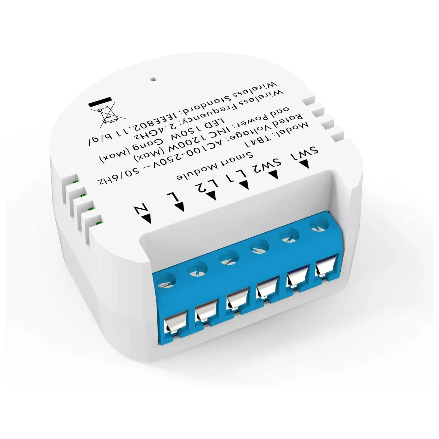
Available from:
Amazon.de
Aliexpress.com
Manufacturer:
Alibaba.com
Install method:
USB to Serial
| GPIO # | Component |
|---|---|
| GPIO00 | LedLinki |
| GPIO01 | None |
| GPIO02 | None |
| GPIO03 | Relay 2 |
| GPIO04 | HLW8012 CF |
| GPIO05 | HLWBL CF1 |
| GPIO09 | None |
| GPIO10 | None |
| GPIO12 | HLWBL SEL |
| GPIO13 | Switch_n 2 |
| GPIO14 | Buzzer |
| GPIO15 | Relay 1 |
| GPIO16 | Switch_n 1 |
| GPIO17 | None |
{"NAME":"Milfra Smart Module TB41","GPIO":[576,0,0,225,2688,2656,0,0,2592,193,480,224,192,0],"FLAG":0,"BASE":18}Since Relay 2 is on UART0 RXD, serial connection to this device isn’t possible.
The Buzzer is configured as BUZZER, but needs a PWM signal to actually buzz - you can configure it as PWM instead.
This device has also a HLW8012 power montior chip included
There are two PCBs inside, one with mostly high voltage stuff and one on top to control it. The logic PCB has solder points for 2mm grid pin headers which are labeled on the backside of the PCB, beware, it’s glued to the case on the connector end of the case.


