


Available from:
Banggood.com
Aliexpress.com
Manufacturer:
Moeshouse.com
| GPIO # | Component |
|---|---|
| GPIO00 | User |
| GPIO01 | User |
| GPIO02 | User |
| GPIO03 | User |
| GPIO04 | User |
| GPIO05 | User |
| GPIO09 | None |
| GPIO10 | None |
| GPIO12 | User |
| GPIO13 | Tuya Rx |
| GPIO14 | User |
| GPIO15 | Tuya Tx |
| GPIO16 | User |
| FLAG | None |
{"NAME":"MOES DS01","GPIO":[255,255,255,255,255,255,0,0,255,108,255,107,255],"FLAG":0,"BASE":54}BLAKADDER when buying from moeshouse.com store for a 20% discount.
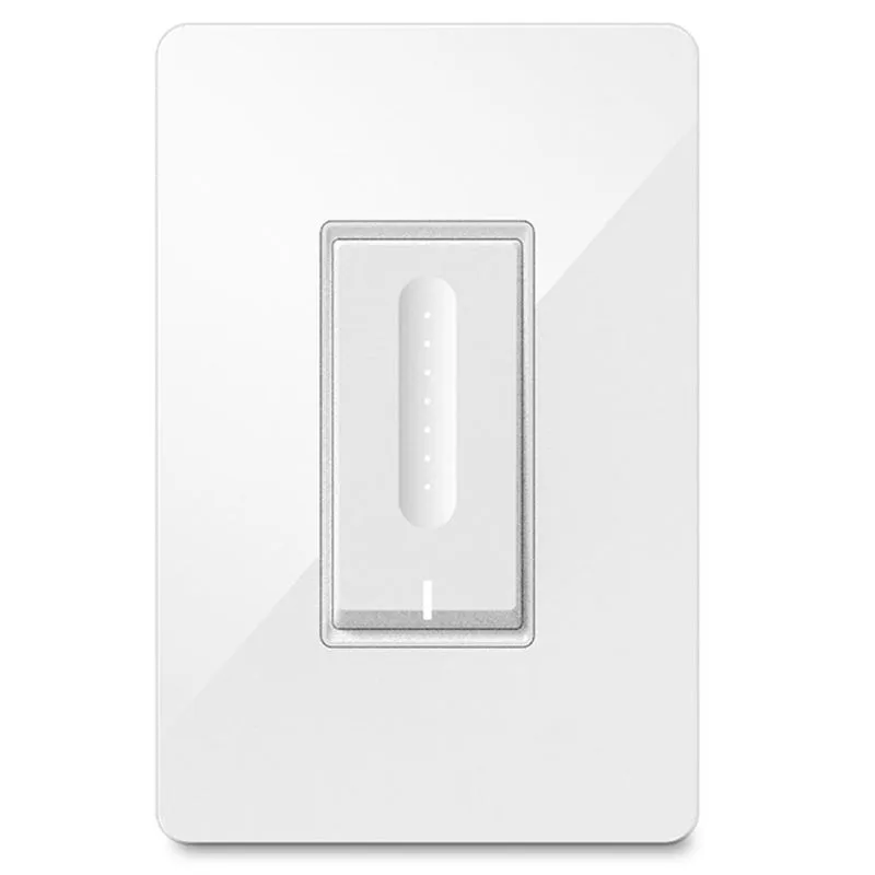
There are several Tuya Dimmer variants by various manufacturers. These dimmers are usually 1 gang switches that dim mains voltage for various lighting types: incandescent, CFL, and LED. Consult the specific device for the type of bulbs and capacity it supports as well as the bulbs themselves to verify they support dimming.
Configuration
These dimmers typically use hardware serial either on GPIO01 and GPIO03, or GPIO13 and GPIO15. Different devices/models vary in which GPIO pair is used. You may need to modify the GPIO assignments to match your specific device hardware.
| GPIO | Component |
|---|---|
| 01 | Tuya Rx (108) |
| 03 | Tuya Tx (107) |
| 13 | Tuya Rx (108) |
| 15 | Tuya Tx (107) |
Post Tasmota version 6.6.0.10
- Goto WebUI and then Console
- Enter commands
TuyaMCU 21,2
If this doesn’t work see https://tasmota.github.io/docs/TuyaMCU
Flashing


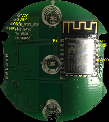
These devices use a Tuya TYWE3S Wi-Fi PCB module. Once the switch is carefully popped open you will need to remove the ribbon cables for flashing and ease of soldering. An easy soldering method is to take several Dupont style jumper wires, cut one end off, and apply a bit of solder to each stripped end. This will keep the wire flexible and prevent any circuit board pads from ripping off. Apply a bit of solder to each pad necessary to flash (double check your pin-outs). Once the wire and pad have solder simply put the two together and apply a bit of heat and they will join together.
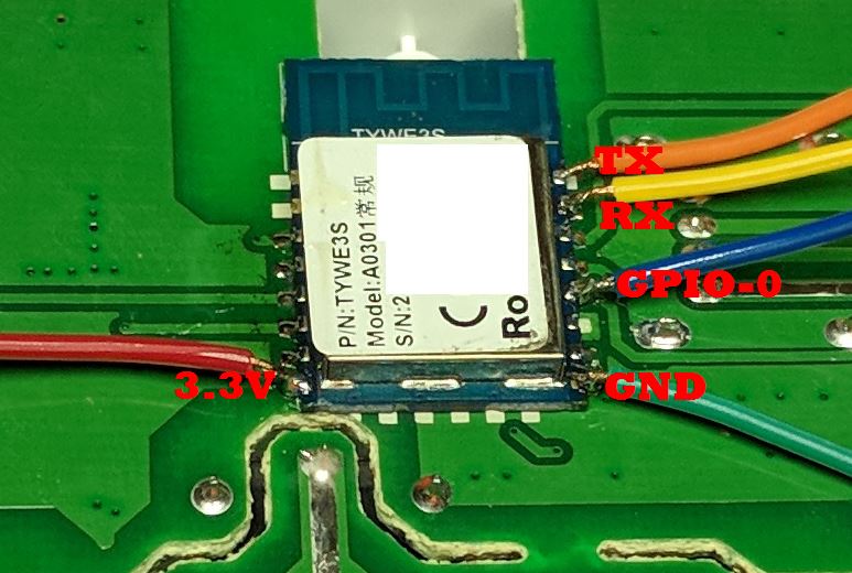
Attach the GPIO0 wire to ground during initial boot to flash. A 3-pin header bridged together works great with GPIO0, GND and the GND from the USB flasher attached. (TX pin to RX pin and RX pin to TX pin on USB flash adapter). Verify that you are using 3.3volts to flash, NOT 5V!
Costco Charging Essentials
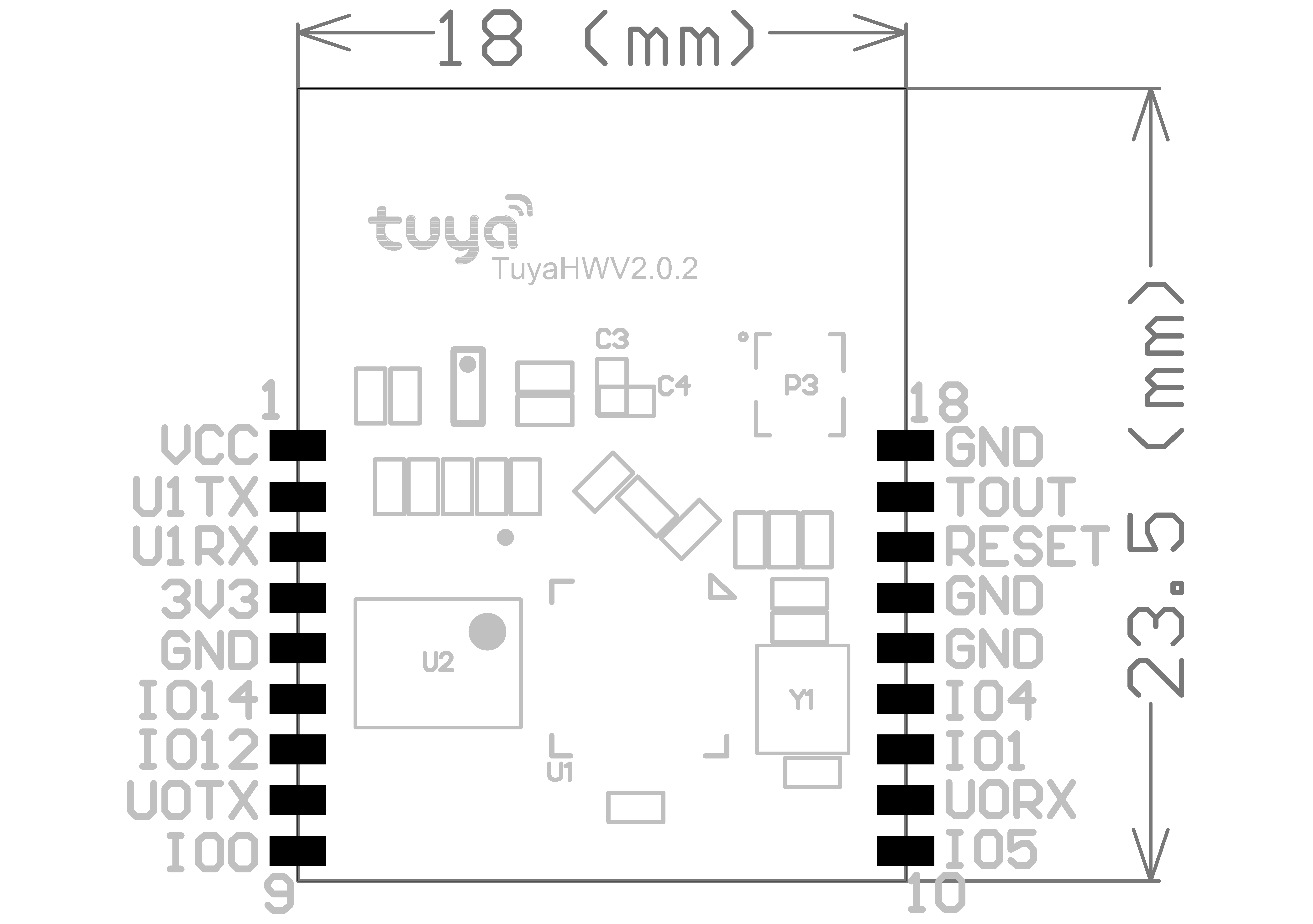
This devices use a Tuya TYWE1S Wi-Fi PCB module. And it uses U1TX (GPIO15) and U1RX (GPIO13) to communicate between ESP8266 and MCU, no other GPIO is used in this device.
Flashing
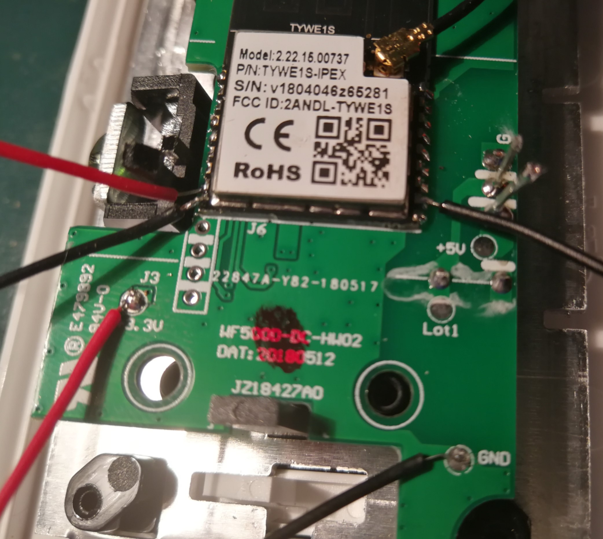
The CE dimmer uses standard Tuya GPIO
Touch (EU and US) - Multiple manufacturers
Flashing
The procedure is similar to above, additionally NRST must be connected to GND during flashing.
Additional configuration
SetOption34 2 (This sets the ID used to set the dim-level)
Optional configuration (recommended)
LedState 0 (To only use the green LED for wifi/mqtt connectivity.)
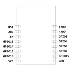
Pinout
 .
.