Available from:
Amazon.de
Amazon.co.uk
Novostella.uk
Manufacturer:
Novostella.uk
Install method:
Tuya-Convert
| GPIO # | Component |
|---|---|
| GPIO00 | None |
| GPIO01 | None |
| GPIO02 | None |
| GPIO03 | None |
| GPIO04 | PWM1 |
| GPIO05 | PWM4 |
| GPIO09 | None |
| GPIO10 | None |
| GPIO12 | PWM2 |
| GPIO13 | PWM5 |
| GPIO14 | PWM3 |
| GPIO15 | None |
| GPIO16 | None |
| FLAG | None |
{"NAME":"Novostella 13W","GPIO":[0,0,0,0,37,40,0,0,38,41,39,0,0],"FLAG":0,"BASE":18}BLAKADDER when buying directly from Novostella for a 10% discount.
WARNING: New Tuya devices have replaced their Wi-Fi module with one incompatible with Tasmota!!!
Tuya-Convert might not be possible for this device since the template was added (2020-01-19).
Model number on bulb: SQPA6012-A
Tuya-Convert OTA Flashing
Updated: 2021/10/31
Newer versions of this bulb cannot be OTA flashed via tuya-convert as of October 2020. Ten devices bought on amazon.de in October 2020 and one device bought on Amazon US in October 2021 were running the newer firmware and needed to be manually flashed
https://github.com/ct-Open-Source/tuya-convert/wiki/Collaboration-document-for-PSK-Identity-02
It seems unlikely at this point that Tuya’s anti-OTA-flashing mitigations can be worked around so manual flashing will be required.
Manual Flashing
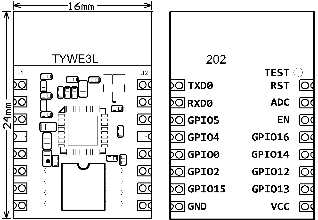
This device uses an ESP8266EX-based Tuya TYWE3L module. It can be flashed manually by attaching a UART adapter to VCC, GND, RX, and TX. To flash the device, make sure to pull GPIO0 to ground on boot then release it for subsequent boots after flashing is complete.

Disassembly Notes
This is of the more difficult bulbs to work with as a fragile interconnect has to be desoldered to get to the ESP module
The diffusion dome can be pulled off after breaking the glue by turning it (no knife necessary). Glue residue must be removed from in between housing and heatsink.
Two screws to need to be removed and and an 8-pin interconnect between the LED PCB and the controller needs to be desoldered. The pads used for this interconnect are fragile and some caution is required to avoid damaging them.
Afterwards, the LED PCB can be pulled off of the heatsink plate. Between these is some thermal paste that may need to be replaced on reassembly.
The heatsink plate can be removed by prying open using a small screwdriver in gap at the edge. This may take a bit of work if a gap isn’t already present.
The control board is covered with a lot of white silicone potting material. This can be removed with a plastic spudger tool or a knife to pull out the PCB a bit and get access to the TYWE3L ESP module.
To get more space the bottom of the bulb can be screwed loose - was easy on 1/4 of the bulbs, possible with decent force on 2/4 of them and impossible on 1/4 bulbs from October 2020. Even without unscrewing the bottom there is just enough space to be able to solder on wires for serial flashing.
For reassembly, do the steps in reverse and resolder the board-to-board interconnect. The interconnect can be very difficult to resolder without bridging, particularly if the solder pads are damaged or if extra solder ends up bridging connections between the boards.


