


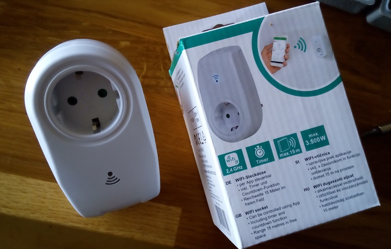
Available from:
Obi.de
| GPIO # | Component |
|---|---|
| GPIO00 | User |
| GPIO01 | User |
| GPIO02 | User |
| GPIO03 | User |
| GPIO04 | Led 1 |
| GPIO05 | Relay 1 |
| GPIO09 | User |
| GPIO10 | User |
| GPIO12 | Led 2 |
| GPIO13 | User |
| GPIO14 | Button 1 |
| GPIO15 | User |
| GPIO16 | User |
| GPIO17 | User |
{"NAME":"Euromate","GPIO":[1,1,1,1,288,224,1,1,289,1,32,1,1,1],"FLAG":0,"BASE":18}{"NAME":"OBI Socket","GPIO":[255,255,0,255,52,21,0,0,54,255,17,0,255],"FLAG":1,"BASE":51}Serial Flashing
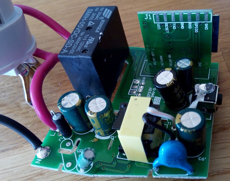
Opening the socket is kind of difficult. If you have one of the Tri-Wing screwdrivers it is much more easier. If you haven’t got use a normal head screwdriver. Be careful not damaging your hand with it.
Tip: Afterwards use normal cross screws to close the casing.
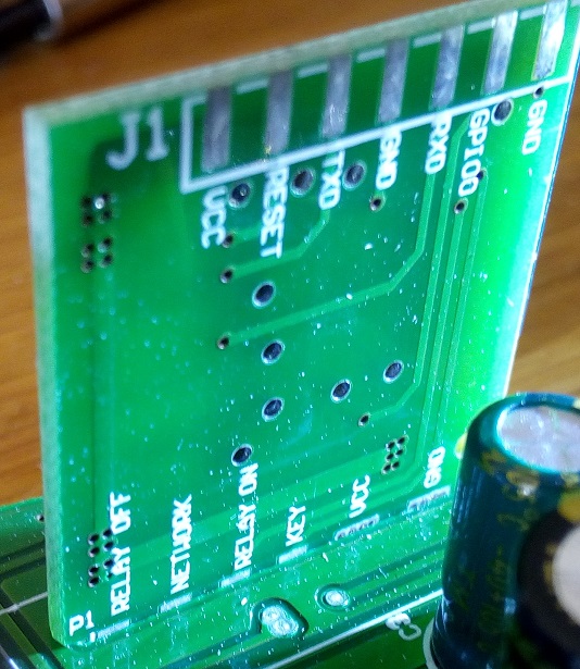
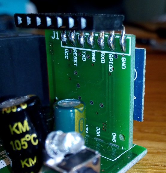
| ESP | Programmer |
|---|---|
| VCC | 3V3 |
| TX | RX |
| RX | TX |
| GND | GND |
Connect GPIO0 to GND before connecting power to enable flash mode!
Additional Information
A low pulse on GPIO12 switches the relay on, a low pulse on GPIO5 switches it off.
I have solved the ‘pulse issue’ by setting GPIO12 to always 0 (as LED) and works fine.
More Infos can be found here: #1988.
Initial Configuration
In the default configuration GPIO0 (which is also used to enable flash-mode) is setup as a Button.
To enable AP-Mode and setup the correct GPIOs as described below,
You can short GPIO0 to GND 4 times as if it was a button (see [[Button-usage]])
Using this method allows you to flash a precompiled binary.
Device Images
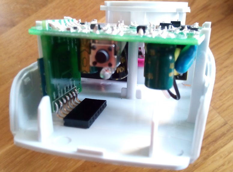
(images from https://github.com/martin-ger/ESP8266-WiFi-Socket)