


Available from:
Amazon.com
Install method:
USB to Serial
| GPIO # | Component |
|---|---|
| GPIO00 | None |
| GPIO01 | None |
| GPIO02 | None |
| GPIO03 | None |
| GPIO04 | Button1 |
| GPIO05 | Relay1 |
| GPIO09 | None |
| GPIO10 | None |
| GPIO12 | None |
| GPIO13 | Led1 |
| GPIO14 | Led2i |
| GPIO15 | None |
| GPIO16 | None |
| FLAG | Analog |
{"NAME":"POWRUI AW-08","GPIO":[0,0,0,0,17,21,0,0,0,52,57,0,0],"FLAG":1,"BASE":18}If you do not want the blue LED to stay on set GPIO13 to LED1i (56) which will turn it off after it boots up.
Serial Connection
If you need to add a serial conneciton to this device for flashing, you will need to folow a few steps.
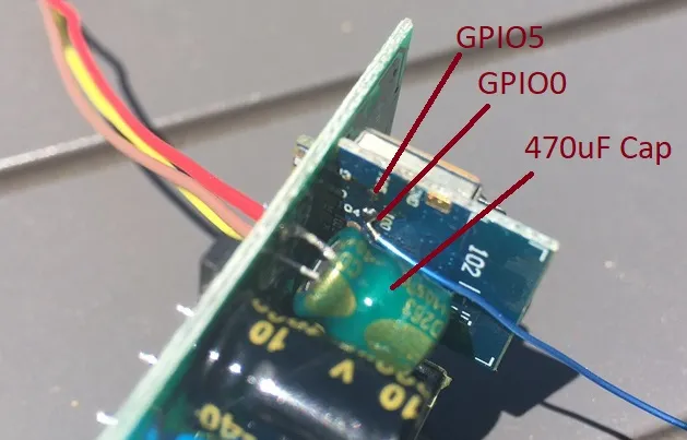
You must open the unit and solder a wire to the GPIO0 pad on the TYWE2S module.
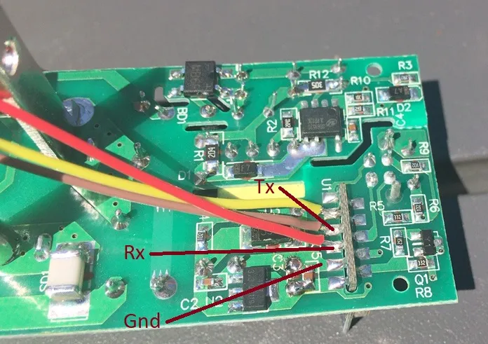
Accessing the UART pins is straightforward on the back side of the PCB.
Opening the unit
A bench vise is an approach that can leave the unit unscathed but still afford access to the PCB. The unit will separate between the outer shell and the base where the plug pins are. Begin by finding a rag or sock and insert the end of the AW-08 into the vice with the rag protecting it - insert the unit at an angle with the plug pins facing the center of the vise. Apply pressure slowly. You will hear a crack but you will see the inside plate bows slightly. Don’t go too far or you can break the PCB. Repeat this on the other end of the unit. Finally repeat the process along the length of the unit by inserting it in the vise approximately 1/4” to 1/2” at an angle near the corner of the vise. Don’t insert the whole thing in the vice at one time. It may take what you think is excessive pressure. Just go slowly and each time you move it, check to see if the base is separated from the outer shell. You should be able to pull the two apart by pulling on the plug pins while holding the outer shell.
Removing the PCB.
Once the base has been separated from the shell, remove the two small screws and save for later. Press down on the base plastic while the pins are on a countertop or other hard surface. The power and ground pins should go through the plastic base with the ground pin being the most stubborn. heating the ground pin may allow you to move it easier.
Serial connection and GPIO0
The GPIO0 pad is on the TYWE2S PCB and is difficult to solder unless you have a sharp angled soldering iron tip.
Removing the 470uF capacitor will help. The capacitor must be re-installed afterwards. Use a piece of 30AWG wire-wrap
wire or similar. Connecting this wire to ground when you power on the unit will allow you to flash it using the UART.
The UART signals are easy to access now that the PCB is removed from the plastic base.
After connecting the serial connections, use an FTDI adapter or similar. The serial settings are 115200 8N1 Xon/Xoff. If you were using Tyua-convert and it didn’t work for you, you should see the ESP8266 retrying access to some undefined access point in the serial console (putty, Arduino IDE, etc.).
Flashing
Make sure you have replaced the 470uF capacitor if you removed it. The negative terminal goes towards the center of the PCB.
Using your favorite ESP8266 flashing tool (e.g. esptool), erase the flash using a 1MB blank file. For example, the blank_1MB.bin file for ESPEasy. Flash the tasmota-lite.bin file onto the device and then upgrade to the full version using the OTA URL in the Tasmota UI.
After you are satisfied all is well, cut or unsolder the wires. Put the PCD back on the base and replace the screws.
The unit should go back together smoothly.
Pictures
Pinout
 .
.