


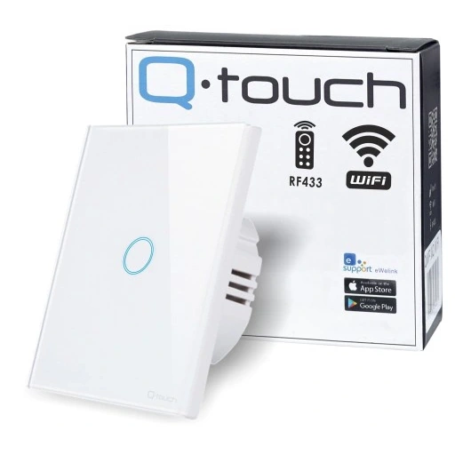
Q-touch 433MHz 1 Gang No Neutral Switch (QWP_W1_WIFI-TOUCH)
Available from:
Allegro.pl
Install method:
USB to Serial
| GPIO # | Component |
|---|---|
| GPIO00 | Button 1 |
| GPIO01 | User |
| GPIO02 | User |
| GPIO03 | User |
| GPIO04 | None |
| GPIO05 | None |
| GPIO09 | None |
| GPIO10 | None |
| GPIO12 | Relay 1 |
| GPIO13 | Led_i 1 |
| GPIO14 | None |
| GPIO15 | None |
| GPIO16 | None |
| GPIO17 | None |
Configuration
{"NAME":"QWP_W1_WIFI-TOUCH","GPIO":[32,1,1,1,0,0,0,0,224,320,0,0,0,0],"FLAG":0,"BASE":28}Programming pins on the top of PCB, six fields (left to right): 3.3V, RX, TX, IO0, RST, GND.
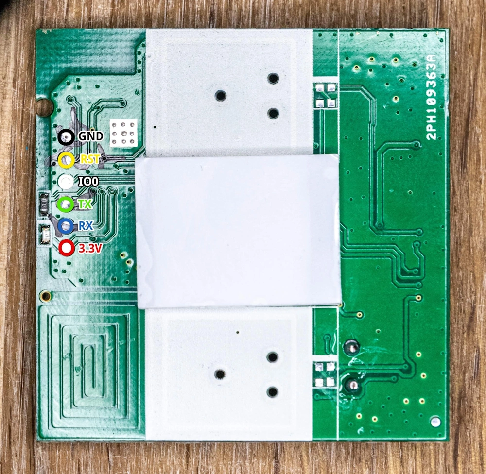
Wire connection:
- 3.3v ———— 3.3v
- Tx ————— Rx
- Rx ————— Tx
- IO0 ————- GND !!!!!!
- GND———— GND
The wall switch signals the states of the relays.
- Relay on - RED touch field illumination
- Relay off - BLUE touch field illumination
After uploading the TASMOTA, the blue highlighting does not work!!! Activate the LedPower function in the console ‘LedPower 1’.