Available from:
Aliexpress.com
Amazon.de
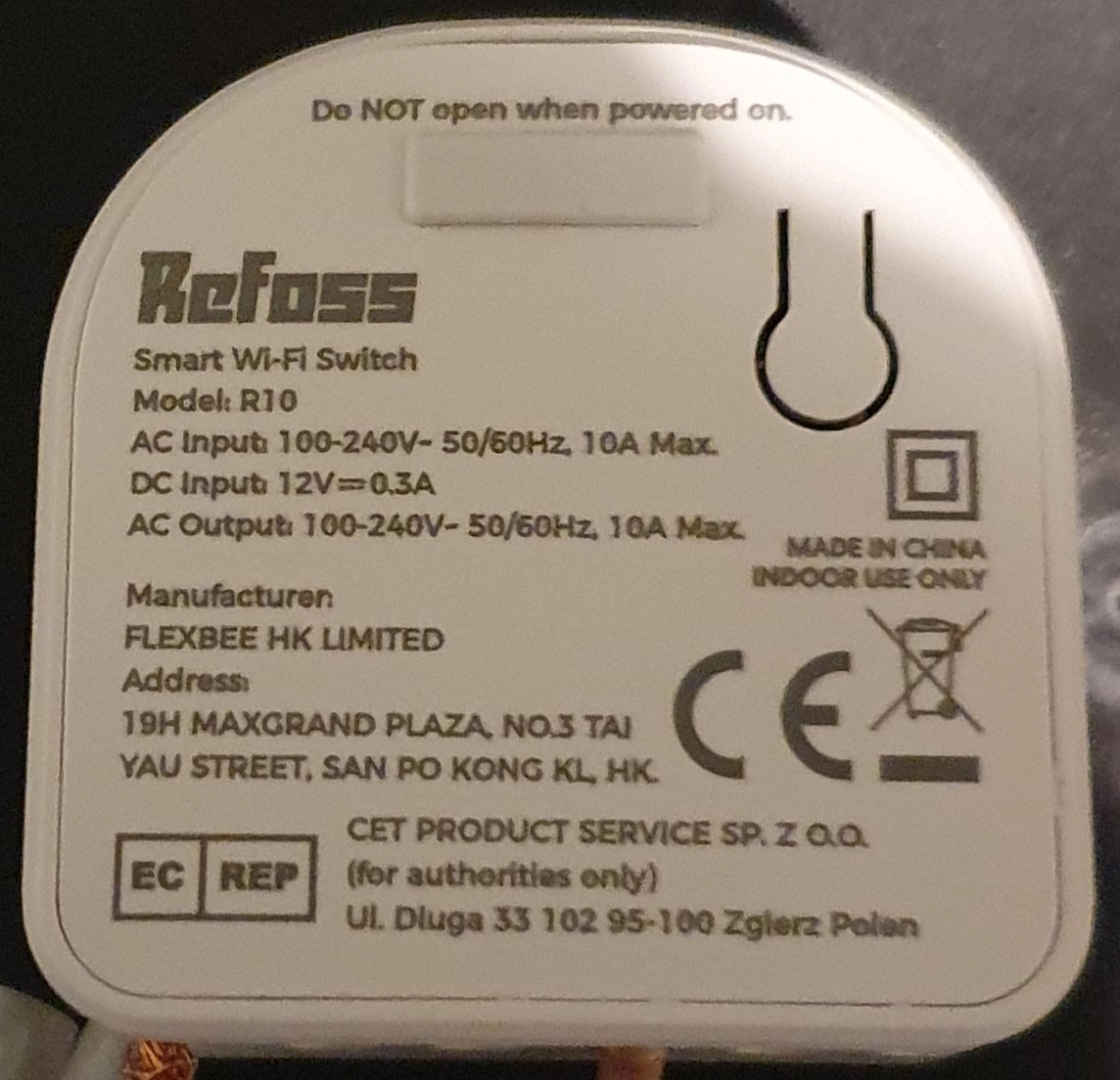
Manufacturer:
Refoss.net
Install method:
USB to Serial
| GPIO # | Component |
|---|---|
| GPIO00 | User |
| GPIO01 | User |
| GPIO02 | None |
| GPIO03 | User |
| GPIO04 | Relay 1 |
| GPIO05 | Switch_n 1 |
| GPIO09 | None |
| GPIO10 | None |
| GPIO12 | HLWBL CF1 |
| GPIO13 | BL0937 CF |
| GPIO14 | Button 1 |
| GPIO15 | User |
| GPIO16 | HLWBL SELi |
| GPIO17 | ADC Temp |
{"NAME":"Refoss-R10","GPIO":[1,1,0,1,224,192,0,0,2656,2720,32,1,2624,4736],"FLAG":0,"BASE":18}SAFETY HAZARD: The digital GND is connected directly to mains voltage “L”, so the GPIOs become LIVE during normal operation.
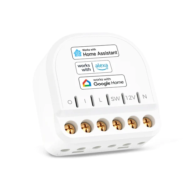
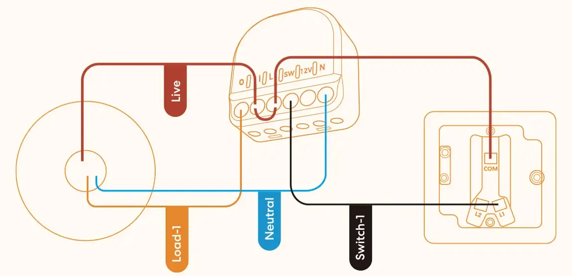
Connection
*Warning: Avoid opening the rubber plug to access the debugging serial port while the device is powered on. *Warning: Do not input AC high voltage into the DC 12V port.
Screw connections O: connects to Pin of relais (connect to lamp) I: connects to other Pin of relais (connect to Live Wire 220V AC) L: 220V AC Live Wire (CAUTION: connected directly to digital GND off ESP8266 !!!) SW: Switch input to GPIO4 using 220V AC input 12V: 12V DC input (testing, usage unclear, do not connect while using 220V AC) N: Neutral AC
Information
-
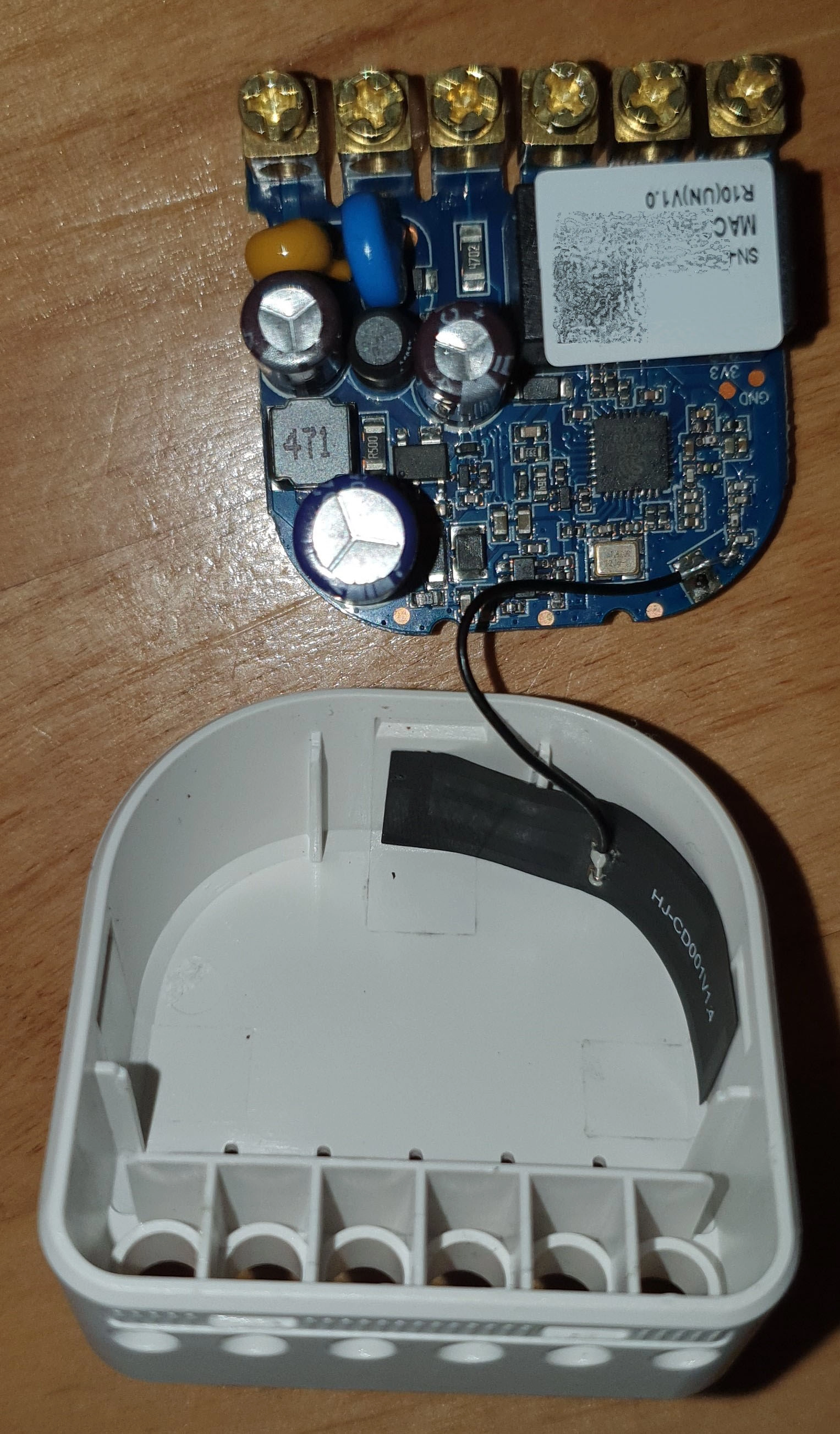
ICs on PCB: ESP8266EX -> Microcontroller; BP2522 -> voltage regulator IC; BL0937 -> Energy Metering IC; BoyaMicro 25Q32 -> Flash IC
-
If the plug keeps turning off for apparently no reason it is likely the wrong factory temperature calibration. Enter command ADCParam1 2, 4000,80000,4250,1 and restart the plug to fix.
-
Installation of Tasmota (and maybe a following reset 5) changes MAC from Vendor 48:E1:E9 (Chengdu Meross Technology Co., Ltd.) to C8:C9:A3(:14) (Espressif Inc.). Also the last 3 Digits are completly different.
-
original firmware button on the backside of the Refoss R10 switches relais. Button is connected to ground (one side) and GPIO-14 (other side). GPIO14 is also connected to 3.3V over 1kOHM resistance (pull up circuit).
Energy Metering IC
-
DataSheet BL0937 6 CF : High frequency pulse output for active power, the pulse width is fixed to 38uS(typical); the frequency is proportional to the active power value. Over-current indication pin; If over-current occurs, the pin output 6.78KHz(typical) pulse; 7 CF1 SEL=0, the output is current RMS, pulse width is fixed to 38uS(typical), The frequency is proportional to the current RMS value; SEL=1, the output is voltage RMS, pulse width is fixed to 38uS(typical), The frequency is proportional to the voltage RMS value; 8 SEL CF1 output select PIN
- BL0937 Pin 6 CF (Power) connected to ESP8266Ex Pin12 GPIO13
- BL0937 Pin 7 CF1 (Current or Volatge, chosen by SEL) connected to ESP8266Ex Pin10 GPIO12
-
BL0937 Pin 8 SEL (Select) connected to ESP8266Ex Pin Pin08 GPIO16
- other devices wih BL0937 are using HLWBL CF, BL0937 CF and HLWBL SEL drivers of Tasmota. HLWBL SEL ist inverted.
Notes
*Hint: Do not change GPIO 5 to ButtonN 1. GPIO as ButtonN 1 results in sporadic resets of tasmota after a while (Tasmota 13.4.0). May be a result of screw connection header connected to GPIO 5 using 220V AC for switching. For use with Ac-conneted button-switches change SwitchMode of SwitchN 1 to inverted pushbutton (default 0, 1 = toggle works fine (Console -> SwitchMode1 4) by typing SwitchMode1 4 in console..
Images
Button on Backside -> seems also connected to GPIO5.
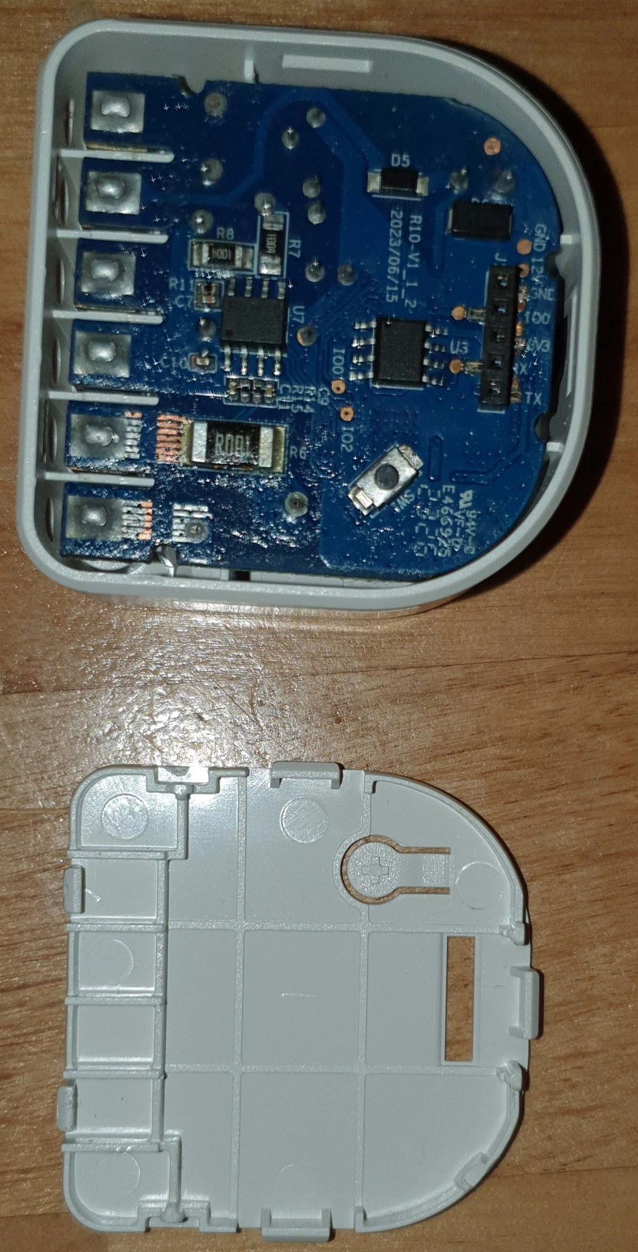
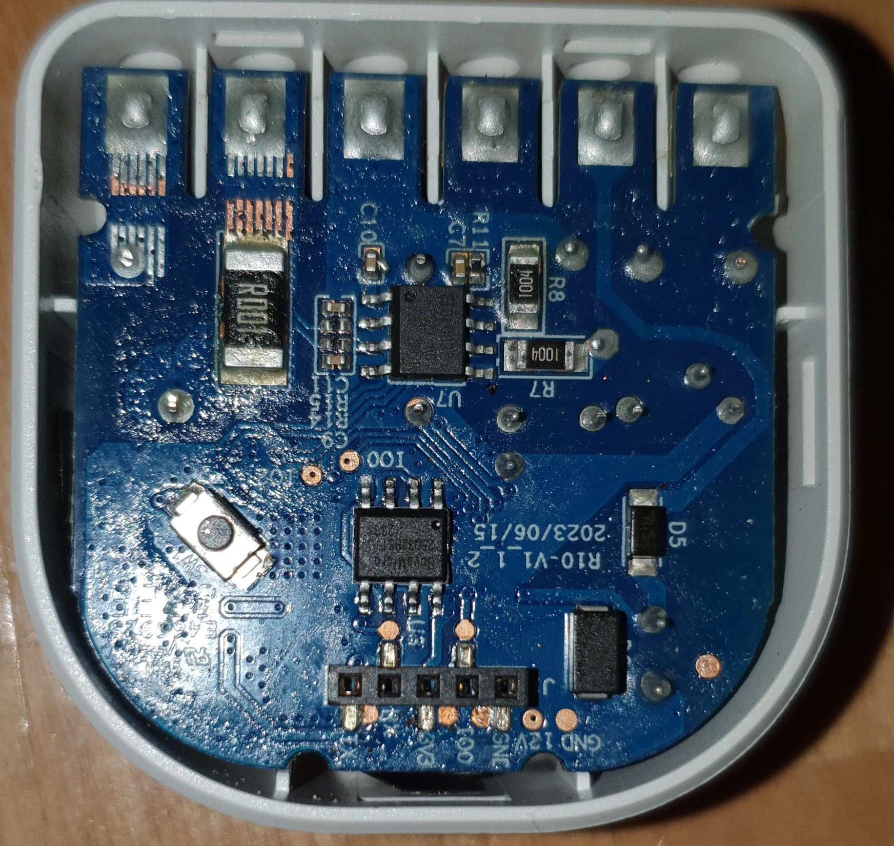
Dupont Pin-Header (2.0mm spacing) under rubber plug on backside (do not use while conneted to 220V AC!!!): GND-IO0-3V3-RX-TX