


Available from:
Shellylb.com
| GPIO # | Component |
|---|---|
| GPIO00 | None |
| GPIO01 | MCP39F5 Tx |
| GPIO02 | None |
| GPIO03 | MCP39F5 Rx |
| GPIO04 | Relay1 |
| GPIO05 | Relay2 |
| GPIO09 | None |
| GPIO10 | None |
| GPIO12 | Switch1 |
| GPIO13 | None |
| GPIO14 | Switch2 |
| GPIO15 | MCP39F5 Rst |
| GPIO16 | None |
| FLAG | None |
{"NAME":"Shelly 2","GPIO":[0,135,0,136,21,22,0,0,9,0,10,137,0],"FLAG":0,"BASE":47}This product has been discontinued
Shelly 2 is discontinued and replaced by Shelly 2.5
The Shelly 2 is fully supported in Tasmota from version 6.2.1.7
⚠️️Special Shelly Attention⚠️️
Do not connect AC power and the serial connection at the same time The GND connection of the Shelly has a 50% chance of being connected to the live AC wire. Connecting serial with your PC will fry your PC.
Do not connect any additional sensors to serial pins. It can at least destroy your Shelly!
Check the correct jumper position before connecting AC power to Shelly 1. If the jumper is set to 12V you will destroy your Shelly!
Shelly 2
An ESP8266 with 2MB flash dual relay device with Energy Monitoring the size of round 45mm.
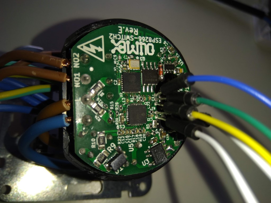
Pins from top to bottom are: TX, RX, +3.3V, GPIO0, GND
Templates as of v6.4.1.17
The inbuilt template equals the following:
{"NAME":"Shelly 2","GPIO":[0,135,0,136,21,22,0,0,9,0,10,137,0],"FLAG":0,"BASE":47}
An alternative template without switch pull-up is:
{"NAME":"Shelly 2n","GPIO":[0,135,0,136,21,22,0,0,82,0,83,137,0],"FLAG":0,"BASE":47}
Pullup or no pullup
The shelly 2 inputs may or may not need pullups for SW1 and SW2 to work correctly. Default state is pullups enabled.
To disable pullups either use command SetOption62 1 or select the option from the GUI.
Refer to the following issue: https://github.com/arendst/Tasmota/issues/4841