


Available from:
Amazon.de
Domadoo.fr
Aliexpress.com
Idealo.de
Install method:
MgOS to Tasmota
| GPIO # | Component |
|---|---|
| GPIO00 | None |
| GPIO01 | None |
| GPIO02 | None |
| GPIO03 | None |
| GPIO04 | None |
| GPIO05 | Led1i |
| GPIO09 | None |
| GPIO10 | None |
| GPIO12 | Switch2n |
| GPIO13 | Switch3n |
| GPIO14 | Switch1n |
| GPIO15 | None |
| GPIO16 | None |
| FLAG | Temperature |
{"NAME":"Shelly i3","GPIO":[0,0,0,0,0,56,0,0,83,84,82,0,0],"FLAG":2,"BASE":18}Internal RST button is located on GPIO4 but not entered in the template until tested.
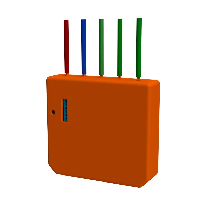
Wiring
Some people face high temperatures with their Shelly i3 in AC installations. To avoid these high temperatures check out the updated AC wiring information in the official Shelly Support Forum
In a nutshell: Switches which are connected to I1, I2 & I3 should be connected to the same wire as the most-right cable of the shelly i3 device, which might say N (blue) instead of L (red).
Configuration
After flashing Tasmota, the Shelly i3 will publish all events of each of the three inputs via “stat/%topic%/POWER” (ON/OFF). But there is no separate POWER1, POWER2 and POWER3. That means that you can only distinguish the state of each switch via the SENSOR data, that is only published every few minutes, but not instantly.
To avoid that issue, the individual switches can publish their own mqtt messages when something changes via Rules in Tasmota.
Commands to be entered via the Tasmota console on your Shelly i3
Backlog Rule1 on Switch1#state do Publish stat/%topic%/SWITCH1 %value% endon on Switch2#state do Publish stat/%topic%/SWITCH2 %value% endon on Switch3#state do Publish stat/%topic%/SWITCH3 %value% endon; Rule1 1; SwitchMode1 1; SwitchMode2 1; SwitchMode3 1; SwitchTopic 0
More about switches and rules