


Available from:
Aliexpress.com
Cloudfree.shop
Banggood.com
Amazon.de
Manufacturer:
Alibaba.com
Install method:
USB to Serial
| GPIO # | Component |
|---|---|
| GPIO00 | User |
| GPIO01 | User |
| GPIO02 | None |
| GPIO03 | User |
| GPIO04 | Button 1 |
| GPIO05 | Relay 1 |
| GPIO09 | None |
| GPIO10 | None |
| GPIO12 | None |
| GPIO13 | None |
| GPIO14 | Led_i 1 |
| GPIO15 | None |
| GPIO16 | LedLink |
| GPIO17 | None |
{"NAME":"XY-WFUSB","GPIO":[1,1,0,1,32,224,0,0,0,0,320,0,544,0],"FLAG":0,"BASE":18}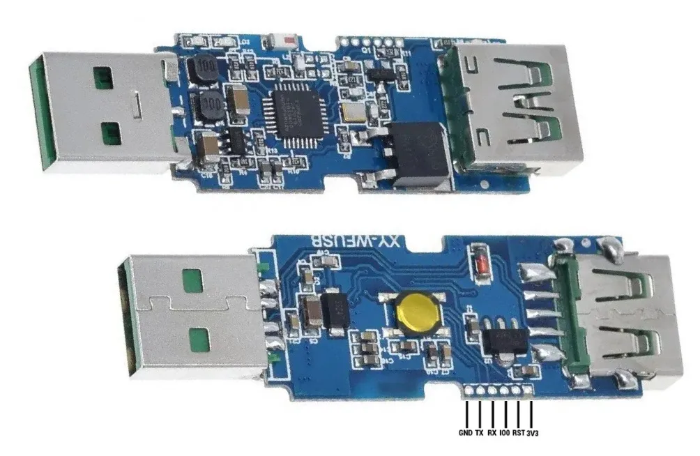
Useful video on flashing from Andreas Spiess
The device has 3 LEDs: (green, blue and red for relay status). Green is wired to GPIO14 and is set to be inverted. By default this means that the LED is on when the relay is off (and vice versa). If you dont want to use this LED, set the GPIO14 port to None. Blue is wired to GPIO16 and is configured as the device status LED. Red is wired to the relay and cannot be configured.
It is possible to use solid core 24 AWG wires to make the connection without needing to solder them to the Sinilink board, but they may need soldering to a connector for the USB to serial adapter. Alternatively, you can strip some Ethernet Cat5e cable, which has the perfect diameter to fit in this board without soldering.
If you use the Sinilink WiFi-USB with PWM-compatible devices such as LED lights or a fan: set GPIO05 to PWM instead of Relay, to control the brightness or rotation speed of the device you plug in.