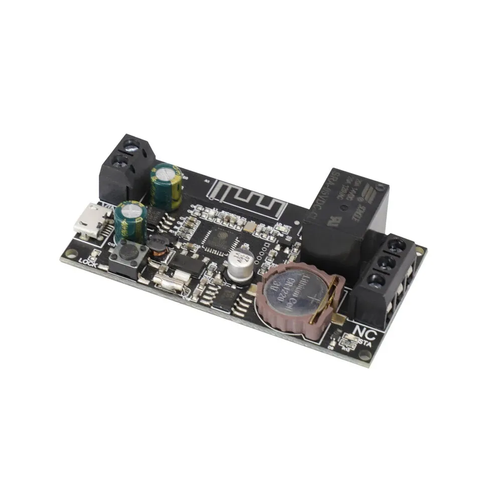
Sinilink 6-32V Real Time Clock Relay Board (XY-WFBJ)

Available from:
Aliexpress.com
Banggood.com
Install method:
USB to Serial
| GPIO # | Component |
|---|---|
| GPIO00 | None |
| GPIO01 | None |
| GPIO02 | LedLink |
| GPIO03 | None |
| GPIO04 | HallEffect |
| GPIO05 | Relay 1 |
| GPIO09 | None |
| GPIO10 | None |
| GPIO12 | I2C SCL 1 |
| GPIO13 | I2C SDA 1 |
| GPIO14 | Button 1 |
| GPIO15 | None |
| GPIO16 | Led 1 |
| GPIO17 | None |
Configuration
{"NAME":"Sinilink XY-WFBJ","GPIO":[0,0,544,0,7584,224,0,0,608,640,32,0,288,0],"FLAG":0,"BASE":18}You cannot use a regular tasmota.bin file. You have to compile by yourself with
#define USE_RTC_CHIPS
#define USE_PCF85363
You can find the pins for flashing near the ESP chip.
Starting with the square on top:
- VCC
- RST
- GPIO0
- RX
- TX
- GND
Use an external power supply!


