


Available from:
Amazon.com
| GPIO # | Component |
|---|---|
| GPIO00 | None |
| GPIO01 | Button 1 |
| GPIO02 | None |
| GPIO03 | Relay 1 |
| GPIO04 | HLWBL CF1 |
| GPIO05 | HLW8012 CF |
| GPIO09 | None |
| GPIO10 | None |
| GPIO12 | Relay 2 |
| GPIO13 | HLWBL SELi |
| GPIO14 | LedLinki |
| GPIO15 | None |
| GPIO16 | None |
| GPIO17 | ??? |
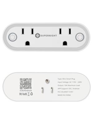
{"NAME":"SUPERNIGHT","GPIO":[0,32,0,224,2656,2688,0,0,225,2624,576,0,0,4833],"FLAG":0,"BASE":18}Tuya Convert worked as of 2021-11-06 (ordered on 2021-11-03). Updated template to include the second button which is an Inverted Analog Button. The TYWE2S pins are completely used by this device. Inverted SEL pin to get properly functioning power monitoring.
Received these in a 2 pack. flashing with OTA was no issue.
I quickly figured out most of the IO.
- GPIO1 = Left Socket Button
- GPIO3 = Left Socket Relay
- GPIO12 = Right Socket Relay
- GPIO14 = Red LED for both buttons
The “night light” seems to be tied to the light sensor only and cannot be turned off. This makes the plug a no-go for me.
Also, I could not figure out the right socket button. I ended up destroying one of the two plugs to see what was inside.
There are 2 circuit boards. One with the Wifi and esp module and another with the buttons and the night lights. On the button board, the trace for the right button is purposely notched for that button so that it doesn’t connect to the header leading to the second circuit board with the esp chip. I’m really wishing I verified that button before flashing as I don’t intend to buy more to test it.
Found this on the issues tracker
Just a quick update. I’ve still not figured out the second button, but I do have energy monitoring working now.
My current pinout is…
- GPIO1 = Left Socket Button
- GPIO3 = Left Socket Relay
- GPIO4 = HLW8012/Voltage (HLWBL CF1)
- GPIO5 = HLW8012 CF Power (HLW8012 CF)
- GPIO12 = Right Socket Relay
- GPIO13 = HLW8012 Output (HLWBL SEL)
- GPIO14 = Red LED for both buttons
Pins 6,7,8 and 11 cause hard resets when I try to set them to switches or buttons.
Pinout
 .
.