


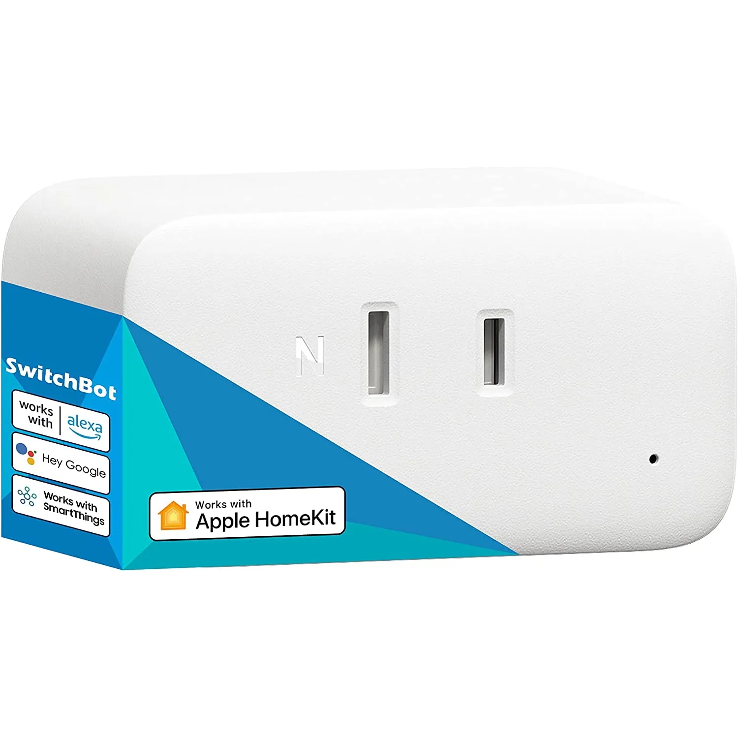
Available from:
Amazon.co.jp
Switchbot.jp
Manufacturer:
Switchbot.jp
Install method:
SwitchbOTA
| GPIO # | Component |
|---|---|
| GPIO00 | None |
| GPIO01 | None |
| GPIO02 | Button 1 |
| GPIO03 | None |
| GPIO04 | None |
| GPIO05 | None |
| GPIO06 | Relay 1 |
| GPIO07 | Led_i 1 |
| GPIO08 | Led_i 2 |
| GPIO09 | None |
| GPIO10 | None |
| GPIO12 | None |
| GPIO13 | None |
| GPIO18 | BL0937 CF |
| GPIO19 | HLWBL CF1 |
| GPIO20 | HLWBL SELi |
| GPIO21 | None |
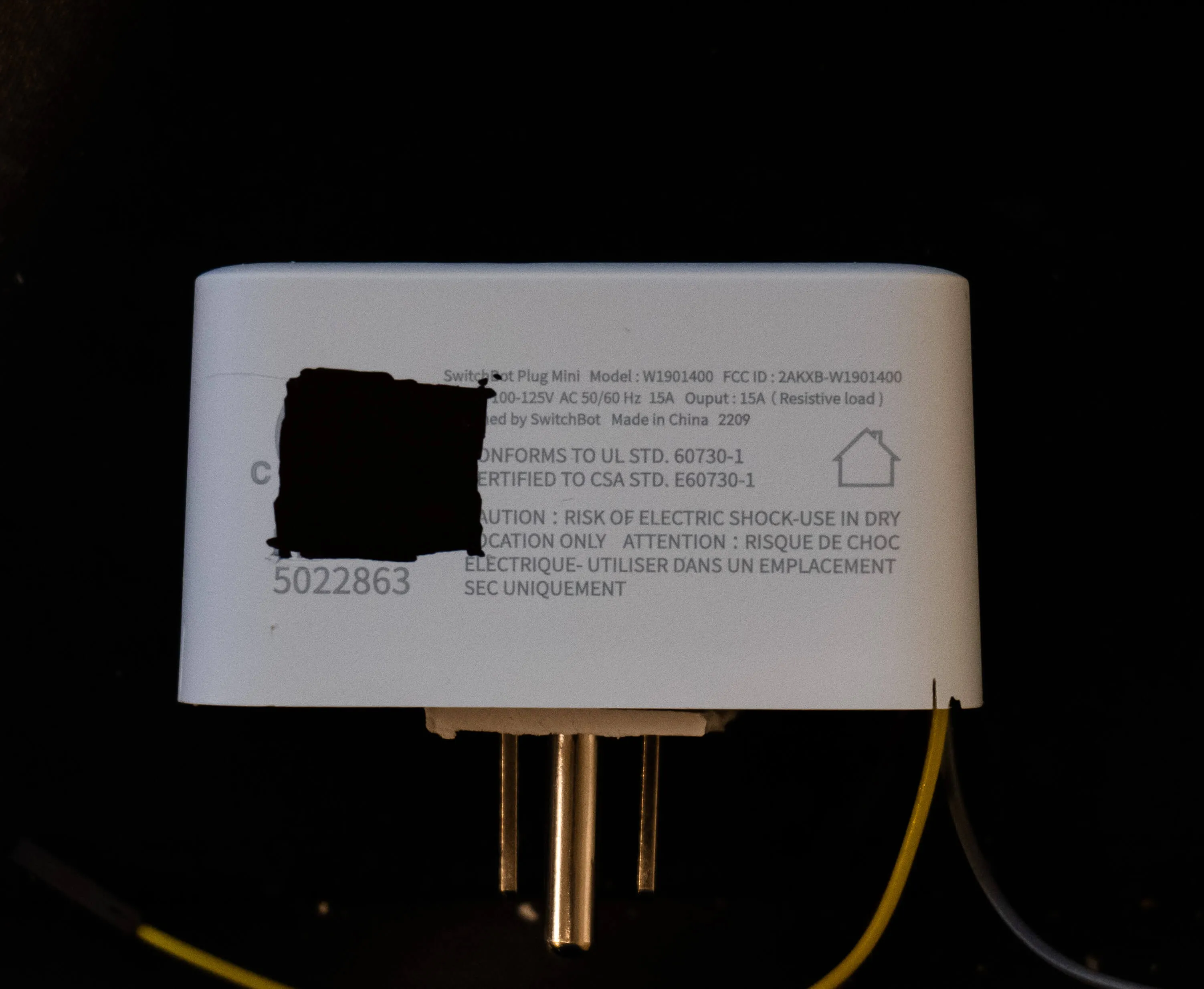
{"NAME":"W2001401","GPIO":[0,0,32,0,0,0,224,320,321,0,0,0,0,0,0,0,0,0,2720,2656,2624,0],"FLAG":0,"BASE":1}Can be flashed over-the-air with SwitchbOTA.
Disassembly
SwitchBot Plug Mini is ultrasonic welded shut. A flat blade screwdriver hammered in the crack has been successfully used to pry it open. (Holding it in a vice may help.) There are no clips, it’s just two plastic pieces that need to be pryed apart. This has been done semi-destructively. (Platic pieces end up marred. Some JB Weld or super glue might reseal it.)
The Plug Mini has programming pads accessible from its side. Cutting the filled area in this photo provides access to the pads:
The daughterboard has clearly labeled pads to allow for programming. Short P9 and GND to place the board into programming mode.
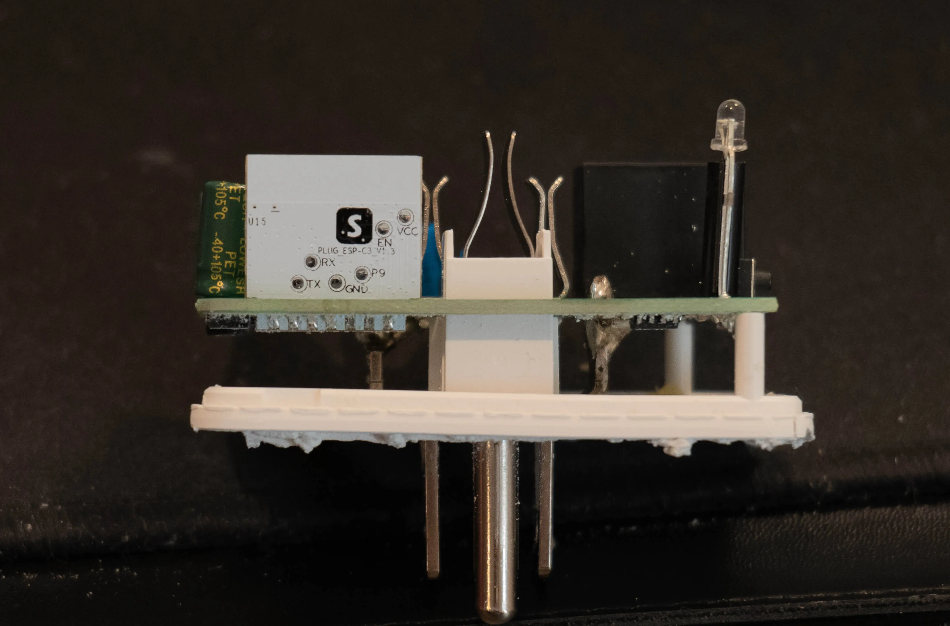
Flashing
Flash using Tasmota Web Installer and select Tasmota ESP32-C3 option.
For esptool.py download f.e. tasmota32c3.factory.bin and run esptool.py write_flash 0x0 tasmota32c3.factory.bin
To put ESP32-C3 in flash mode GPIO8 needs to be pulled high and GPIO9 pulled low.