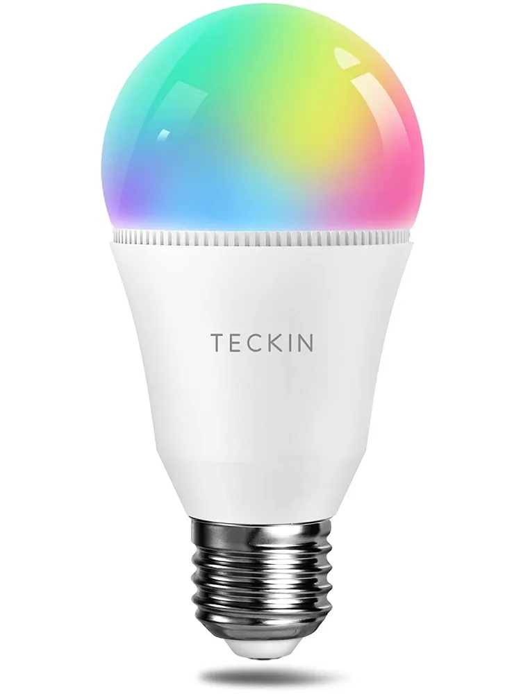
Available from:
Amazon.it
Manufacturer:
Teckinhome.com
Install method:
Replace module
| GPIO # | Component |
|---|---|
| GPIO00 | None |
| GPIO01 | None |
| GPIO02 | None |
| GPIO03 | None |
| GPIO04 | PWM 1 |
| GPIO05 | PWM 4 |
| GPIO09 | None |
| GPIO10 | None |
| GPIO12 | PWM 2 |
| GPIO13 | None |
| GPIO14 | PWM 3 |
| GPIO15 | None |
| GPIO16 | None |
| GPIO17 | None |
{"NAME":"Teckin SB60","GPIO":[0,0,0,0,416,419,0,0,417,0,418,0,0,0],"FLAG":0,"BASE":18}{"NAME":"Teckin SB60 ESP-01D","GPIO":[0,0,0,0,0,0,0,0,4069,0,4032,0,0,0],"FLAG":0,"BASE":18}
See Tasmota documentation on how to configure RGBW lights to your needs.
Note: All units as of August 2020 come with new Tuya firmware and are not compatible with Tuya-Convert.
When replacing with ESP-01D use this template: {"NAME":"Teckin SB60 ESP01D","GPIO":[0,0,0,0,0,0,0,0,4069,0,4032,0,0,0],"FLAG":0,"BASE":18}

Instructions for old SB60 with ESP8266
To regain the original CCT functionality of this bulb, after flashing it, use the following commands in the console.
SetOption106 1
SetOption107 0
This will enable soft-CCT emulation, replicating the missing yellow channel that the Tuya firmware natively emulates in this way.
Hardware Flashing
To hardware flash these bulbs, you need to open them.
Step 1
Start by trying to twist the light-dome cover to break it free from the adhesive. If the cover won’t twist due to excess adhesive, instead grab the dome and try to pull it up on one side. Keep moving around the bulb until you find the side that releases a bit. Stick a knife or spludger into the section that raises the most and use the knife as leverage to separate the dome from the bulb.
Step 2
Using a sharper knife with a stronger blade, get between the diffuser lens and the LED PCB and gently pry the diffuser lens off of the circuit board.
Step 3
Remove the two philips screws and remove the LED board.
Step 4
Solder your USB to UART Serial converter to the PCB pads on the inner board in the positions shown in the image below.

Step 5
Flash the chip with Tazmotizer, ESPTool, or similar.
Step 6
Reassemble the bulb and set it up using the above config and run the additional commands for Soft-CCT if desired.


