


Available from:
Aliexpress.com
Amazon.de
Manufacturer:
Teekar.de
Install method:
Tuya-Convert
| GPIO # | Component |
|---|---|
| GPIO00 | None |
| GPIO01 | Serial Rx |
| GPIO02 | PWM1 |
| GPIO03 | Serial Tx |
| GPIO04 | I2C SDA |
| GPIO05 | I2C SCL |
| GPIO09 | None |
| GPIO10 | None |
| GPIO12 | Switch1 |
| GPIO13 | None |
| GPIO14 | None |
| GPIO15 | None |
| GPIO16 | None |
| FLAG | None |
{"NAME":"Teekar UIW001-","GPIO":[0,149,37,148,6,5,0,0,9,0,0,0,0],"FLAG":0,"BASE":18}Tuya-Convert might not be possible for this device since the template was added (2019-12-31).

To use the script, you have to compile Tasmota with Scripting enabled. Download unofficial precompiled firmware from development branch.

Description
This is one of the rare EU style light dimmers that have a physical power button and a capacitive touch dimming slider with an 8 segment LED display for dimmer value.
Dimmer arrived with a filament LED bulb (regular, non-smart kind) in a cardboard box with german and english instructions and practical wire labels which is a very nice touch.


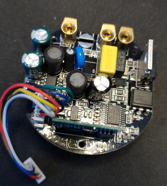
The dimmer circuit is mosfet based with a secondary MCU (STM8S003F3) responsible for dimming. With Tuya firmware and Tasmota the dimming on lower values (below 30%) using the provided bulb produced a lot of flicker. When I switched to a classic incandescent bulb the flicker was completely gone.
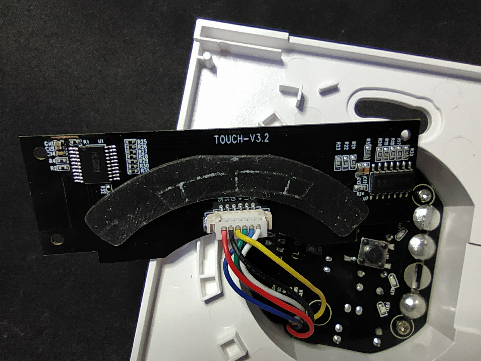
Main dimmer PCB is labelled FL-D1-V1.3, module board is FL-W2SA-V2.0 with an ESP8266. There is a third board labelled TOUCH-V3.2, connected to the main PCB with a labelled cable. It contains the 8 LEDs controlled by a TI HC164 shift register and 8 touch pads controlled by an I2C IC labelled HLS028. Sadly there’s no information on the internet indicating which chip is that. All that’s known is that its a TSSOP20 format and its I2C address is 0x56. I’ve tried getting some information from Teekar directly but they refused to divulge any.

Features
Communication between ESP and the STM8 MCU is one way only and uses a non-standard protocol.
Serial command 65AA000105000000000015 turns the light off while command 65AA0001050000000xx0yy turns it on to the dimmer value. Here xx is dimmer value in the range of 66 to 178 and yy is checksum calculated with “sum of bytes modulo 256”.
8 segment LED shows dimmer status.
The Bad News
Since the capacitive touch pad chip is unknown, there’s no way to use the dimmer slider for physical control in Tasmota.Hopefully someone can sniff out the protocol with proper gear and we can put the touch pad to use in the future.
Front plate switch is constantly lit with LEDs which aren’t connected to GPIOs and cannot be turned off in Tasmota.
That huge front logo is completely unnecessary and, unfortunately, destroys the very nice aesthetic. It is silkscreened very well and couldn’t be removed with mild solvents.
Pinouts

| JST | ESP8266 | |
|---|---|---|
| SDA | GPIO4 | HLS028 SDA |
| SCL | GPIO5 | HLS028 SCL |
| GND | GND | |
| 3V3 | VCC | |
| LEDS | GPIO14 | A and B on HCL164 |
| CLK | GPI015 | CLK on HCL164 |
Front plate switch is connected to GPIO12.
Configuration
Tuya-Convert is the more convenient option for installing Tasmota but it is possible to flash over serial. Use the following pinout and ground the GPIO0 directly on the ESP8266 pin which is quite hard to reach.
Apply the template and issue:
Backlog SwitchMode3; PowerRetain 1
Open Configuration -> Edit script in the web UI and paste the contents of the script in the window. Check script enable and Save.
Script:
;by blakadder
;inspired by thxthx0 QS-WiFi-D01 dimmer script

>D 30
p:dimval=70 ;starting value if none is saved
tmp=0
powert=0
slider=0
dim=""
dimc=
tmin=66   ;dim min
tmax=178  ;dim max

>B
; open pins for shift register
spinm(14 1)
spinm(13 1)
=>print Teekar-Dimmer-Script-v0.5
=>Baudrate 9600
if pwr[1]==1
then
powert=1
else
powert=0
endif

>E
slider=Dimmer
if chg[slider]>0
then
if slider>0
then
dimval=slider
else
powert=0
endif
endif

if pwr[1]==1
; on/off webui
then
powert=1
=#senddim(dimval)
else
powert=0
=#senddim(0)
=#0
endif

;dim subroutine
#senddim(tmp)
dimc=((tmp-1)/99)*(tmax-tmin)+tmin
dim="65AA000105000000"+hn(dimc)+"00"+hn((277+dimc)%256)
if tmp==0
then =>SerialSend5 65AA000105000000000015
else =>SerialSend5 %dim%
endif
=> Dimmer %tmp%
svars ;saves dimval to flash
;control LED slider
if tmp>0
then =#1
endif
if tmp>14
then =#2
endif
if tmp>28
then =#3
endif
if tmp>42
then =#4
endif
if tmp>56
then =#5
endif
if tmp>70
then =#6
endif
if tmp>84
then =#7
endif
if tmp>98
then =#8
endif
#

;led slider subroutines
#c
spin(13 0)
spin(13 1)
#
#c4
=#c
=#c
=#c
=#c
#
#dh
spin(14 1)
#
#dl
spin(14 0)
#
#0
=#dh
=#c4
=#c4
#
#1
=#dh
=#c4
=#c
=#c
=#c
=#dl
=#c
#
#2
=#dh
=#c4
=#c
=#c
=#dl
=#c
=#c
#
#3
=#dh
=#c
=#c4
=#dl
=#c
=#c
=#c
#
#4
=#dh
=#c4
=#dl
=#c4
#
#5
=#dl
=#c
=#dh
=#c
=#c
=#c
=#dl
=#c4
#
#6
=#dl
=#c
=#c
=#dh
=#c
=#c
=#dl
=#c4
#
#7
=#dl
=#c
=#c
=#c
=#dh
=#c
=#dl
=#c4
#
#
#8
=#dl
=#c4
=#c4
#