


Available from:
Amazon.com
Amazon.com
Manufacturer:
Treatlife.tech
Install method:
Tuya-Convert
| GPIO # | Component |
|---|---|
| GPIO00 | None |
| GPIO01 | Tuya Tx |
| GPIO02 | None |
| GPIO03 | Tuya Rx |
| GPIO04 | None |
| GPIO05 | None |
| GPIO09 | None |
| GPIO10 | None |
| GPIO12 | None |
| GPIO13 | None |
| GPIO14 | None |
| GPIO15 | None |
| GPIO16 | None |
| FLAG | None |
{"NAME":"DS02S Dimmer","GPIO":[0,107,0,108,0,0,0,0,0,0,0,0,0],"FLAG":0,"BASE":54}Tuya-Convert might not be possible for this device since the template was added (2019-12-09).
Update 2020-11-13
Tuya-Convert does not work anymore you need to hard flash the chip directly with USB TTL cable (3.3v)
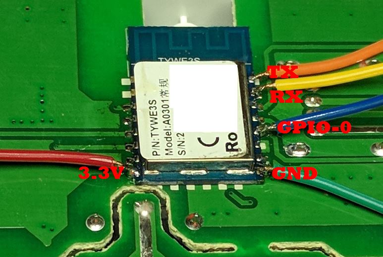
Attach the GPIO0 wire to ground during initial boot to flash.
A 3-pin header bridged together works great with GPIO0, GND and the GND from the USB flasher attached.
(TX pin to RX pin and RX pin to TX pin on USB flash adapter). Verify that you are using 3.3volts to flash, NOT 5V!
–
Update 2021Jan26: If flashing fails: Its been reported that only CP2102 flashers have been known to work directly (also said to require an external power supply).
Issue is that the secondary MCU TX is also connected to the ESP RX line. Known method of preventing interference is to cut the trace for this connection (and resolder after flashing).
With cutting of the trace usual flashers can work. Its been suggested that perhaps CP2102 flashers overpower the 2nd MCU signal.
The trace to cut is the light green area between lines 3 and 4 in this picture. After flashing, use an exacto knife to expose copper 1mm on either side and solder.
 chip_wireschip_wires
Above information was collected from:
See notes below this video:
https://www.youtube.com/watch?v=jticF3ZtEo4
And this thread contains the source of the trace cutting process:
https://www.reddit.com/r/tasmota/comments/j6gqf4/tuya_dimmers_with_a_bf7612_mcu_in_it/g7yl68a/
—
After flash and update to current release tasmota.bin :
chip_wireschip_wires
Above information was collected from:
See notes below this video:
https://www.youtube.com/watch?v=jticF3ZtEo4
And this thread contains the source of the trace cutting process:
https://www.reddit.com/r/tasmota/comments/j6gqf4/tuya_dimmers_with_a_bf7612_mcu_in_it/g7yl68a/
—
After flash and update to current release tasmota.bin :
- Go to WebUI and then Console
- Enter command
TuyaMCU 21,2 - Set Dimmer Range with
DimmerRange 150,1000
Now Dimmer Command should work from 0-100.
If no dimming occurs try changing the dimming mode:
- Dimming Mode 1:
SerialSend5 55AA00060005040400010013 - Dimming Mode 2:
SerialSend5 55AA00060005040400010114 - Dimming Mode 3:
SerialSend5 55AA00060005040400010215
Dimming mode is reset after every reboot so add a rule at system boot.
Rule1 on system#boot do SerialSend5 55AA00060005040400010114 endon
Enable with Rule1 1
The main button turns the switch on/off if single-clicked.
If you double-click it, the brightness set point is reset to the stored favorite value (or 50.5% if no value has been stored since reset) - note that this won’t turn the switch on or off, just set the brightness with the switch staying on or off.
If you triple-click it, the current brightness set point will be stored as the new favorite (overwriting the previous saved value).