


Available from:
Unexpectedmaker.com
Manufacturer:
Esp32s3.com
Install method:
USB to Serial
| GPIO # | Component |
|---|---|
| GPIO00 | User |
| GPIO01 | User |
| GPIO02 | ADC Input 1 |
| GPIO03 | User |
| GPIO04 | ADC Light |
| GPIO05 | User |
| GPIO06 | User |
| GPIO07 | User |
| GPIO08 | User |
| GPIO09 | User |
| GPIO10 | User |
| GPIO11 | User |
| GPIO12 | User |
| GPIO13 | Led 1 |
| GPIO14 | User |
| GPIO15 | None |
| GPIO16 | None |
| GPIO17 | User |
| GPIO18 | User |
| GPIO19 | None |
| GPIO20 | None |
| GPIO21 | None |
| GPIO33 | User |
| GPIO34 | None |
| GPIO35 | User |
| GPIO36 | User |
| GPIO37 | User |
| GPIO38 | User |
| GPIO39 | Output Hi |
| GPIO40 | WS2812 1 |
| GPIO41 | None |
| GPIO42 | None |
| GPIO43 | Serial Tx |
| GPIO44 | Serial Rx |
| GPIO45 | None |
| GPIO46 | None |
| GPIO47 | None |
| GPIO48 | None |
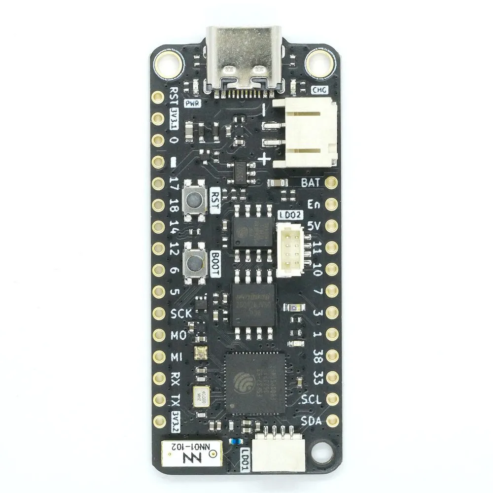
{"NAME":"FeatherS3","GPIO":[1,1,4704,1,4768,1,1,1,1,1,1,1,1,288,1,0,0,1,1,0,0,0,1,0,1,1,1,1,3840,1376,0,0,3200,3232,0,0,0,0],"FLAG":0,"BASE":1}A Feather form factor ESP32-S3 dev board with 1S LiPo battery monitoring.
This board uses an ESP32-S3 chip with no onboard flash or PSRAM with an external 16 MB SPI flash chip and an external 8MB PSRAM chip.
When the board is booted into debug by holding BOOT and pressing the RESET button the USB-Serial chip on the USB port exposes a serial connection. This can be used to easily flash new firmware.
Flashing
Flash using Tasmota Web Installer and select Tasmota ESP32-S3 option.
For esptool.py download f.e. tasmota32s3.factory.bin and run esptool.py write_flash 0x0 tasmota32s3.factory.bin
To put ESP32-S3 in flash mode GPIO0 needs to be pulled low.
Device Notes


Peripherals
WS2812BNeopixel- On
GPIO40(configured asWS2812) with power onGPIO39(configured asOutput Hi).
- On
- 1x Blue Status LED
- On
GPIO13(configured asLED 1).
- On
- 1x Ambient light sensor (
ALS-PT19)- On
GPIO4(configured asAnalog2).
- On
- 2x STEMMA-QT JST-SH I2C bus connector
- Both ports share the same bus, on
GPIO9(SCL) andGPIO8(SDA) (configured asI2C 1). These ports are on the same bus as theSCLandSDApins labelled on the board.
- Both ports share the same bus, on
- 1S LiPo battery management subsystem with 2-pin JST-PH connector
- Battery voltage divider on
GPIO2(configured asAnalog1) and 5V/USB voltage detection onGPIO34(not configured)
- Battery voltage divider on
GPIO Pin Mapping
The user pins labelled on the board are set up as User pins in the template.The pin numbers match the ESP’s internal GPIO number assignments allowing relatively easy module configuration without having to translate pin.
The only exception are the pins labeled TX and RX, which are set up as Serial TX/RX in the template.