


Available from:
Amazon.com
Unexpectedmaker.com
Shop.pimoroni.com
Manufacturer:
Unexpectedmaker.com
Install method:
USB to Serial
| GPIO # | Component |
|---|---|
| GPIO00 | User |
| GPIO01 | WS2812 1 |
| GPIO02 | Output Hi |
| GPIO03 | ADC Input 1 |
| GPIO04 | User |
| GPIO05 | User |
| GPIO06 | User |
| GPIO07 | User |
| GPIO08 | User |
| GPIO09 | User |
| GPIO10 | None |
| GPIO11 | None |
| GPIO12 | None |
| GPIO13 | None |
| GPIO14 | User |
| GPIO15 | None |
| GPIO16 | None |
| GPIO17 | User |
| GPIO18 | User |
| GPIO19 | None |
| GPIO20 | None |
| GPIO21 | None |
| GPIO33 | User |
| GPIO34 | None |
| GPIO35 | User |
| GPIO36 | User |
| GPIO37 | User |
| GPIO38 | User |
| GPIO39 | None |
| GPIO40 | None |
| GPIO41 | None |
| GPIO42 | None |
| GPIO43 | Serial Tx |
| GPIO44 | Serial Rx |
| GPIO45 | None |
| GPIO46 | None |
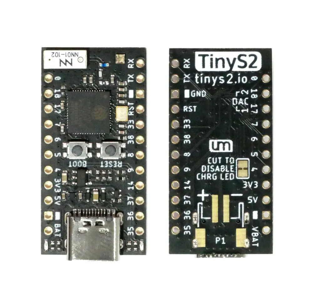
{"NAME":"TinyS2","GPIO":[1,1376,3840,4704,1,1,1,1,1,1,0,0,0,0,1,0,0,1,1,0,0,0,1,0,1,1,1,1,0,0,0,0,3200,3232,0,0],"FLAG":0,"BASE":1}A small form factor ESP32-S2 dev board.
This board uses an ESP32-S2F-N4R2 chip with 4 MB of flash and 2 MB of PSRAM.
When the board is booted into debug by holding BOOT and pressing the RESET button the USB port exposes a serial connection. This can be used to easily flash new firmware.
Flashing
Flash using Tasmota Web Installer and select Tasmota ESP32-S2 option.
For esptool.py download i.e. tasmota32s2.factory.bin and run esptool.py write_flash 0x0 tasmota32s2.factory.bin
To put ESP32-S2 in flash mode GPIO0 needs to be pulled low.
Device Notes

There are two versions of the TinyS2 with slightly different pinouts for the SPI pins.


Peripherals
WS2812BNeopixel- On
GPIO1with power onGPIO2. - Provided template configures this as
WS2812withGPIO2asOutput Hifor power.
- On
- 1S LiPo battery management subsystem with 2-pin JST-SH connector
- Battery voltage on
GPIO3and 5V/voltage detection onGPIO21 - Provided template configures
GPIO3asADC Input 1and does not configureGPIO21.
- Battery voltage on
GPIO Pin Mapping
The user pins labelled on the board are set up as User pins in the template.The pin numbers match the ESP’s internal GPIO number assignments allowing relatively easy module configuration without having to translate pin.
The only exception are the pins labeled TX and RX, which are set up as Serial TX/RX in the template.