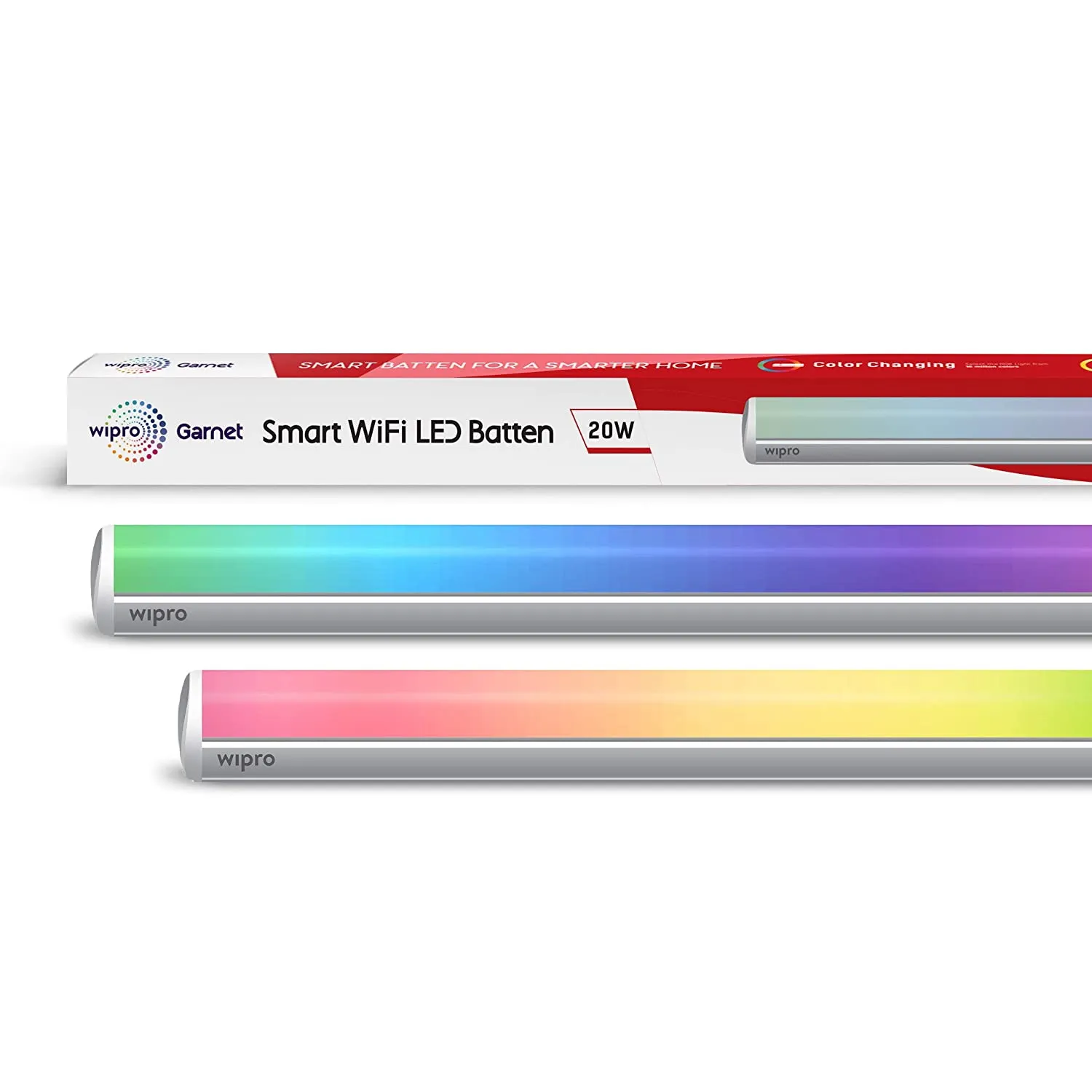
Available from:
Amazon.in
Install method:
USB to Serial
| GPIO # | Component |
|---|---|
| GPIO00 | None |
| GPIO01 | None |
| GPIO02 | None |
| GPIO03 | None |
| GPIO04 | PWM 1 |
| GPIO05 | PWM 4 |
| GPIO09 | None |
| GPIO10 | None |
| GPIO12 | PWM 2 |
| GPIO13 | PWM 5 |
| GPIO14 | PWM 3 |
| GPIO15 | None |
| GPIO16 | None |
| GPIO17 | User |
{"NAME":"Wipro RGBW Tubelight","GPIO":[0,0,0,0,416,419,0,0,417,420,418,0,0,1],"FLAG":0,"BASE":18}Remove caps from both ends, desolder the three wires (Black, White, Yellow), push the power wire through the rubber gasket holding the power wire in place and pull out the module on the opposite end (opposite to where we desoldered the three wires).
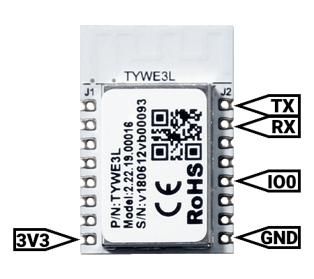
There is a TYWE3L module inside, look up the pinout and link USB serial flasher accordingly (I swapped RX and TX for mine). Do not forget to connect GND to GPI0 before plugging in the USB flasher. Plug in the flashing device and flash the full image (not minimal/sensors). Once flashed, test the module by powering it on with only VCC and GND connected. You should be able to configure the Wifi network at this stage (connect to TASXXX network through a cell phone/laptop and choose sign in). If not, reflash and repeat until successful.
Once configured, disconnect device from flasher and resolder the three wires we disconnected in the first step. You can now connect the power cable to mains, navigate to the IP address, use this template and test it - be very careful connecting the device to mains and do not touch it while it is connected. Test whether all the lights work as intended. If not, disconnect, reflash and retry until successful.
Once done, insert the module back into the body and put the end caps back on. Instal as required.”
Pinout
 .
.


