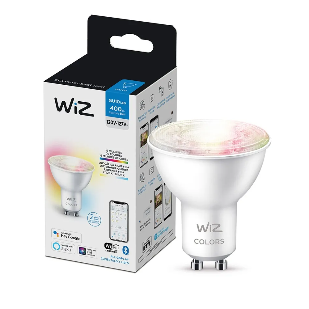
Available from:
Homedepot.com.mx
Amazon.com.br
Manufacturer:
Wizconnected.com
Install method:
USB to Serial
| GPIO # | Component |
|---|---|
| GPIO00 | None |
| GPIO01 | None |
| GPIO02 | PWM 5 |
| GPIO03 | None |
| GPIO04 | PWM 4 |
| GPIO05 | PWM 1 |
| GPIO09 | None |
| GPIO10 | None |
| GPIO12 | None |
| GPIO13 | None |
| GPIO14 | None |
| GPIO15 | None |
| GPIO16 | None |
| GPIO17 | None |
| GPIO18 | PWM 2 |
| GPIO19 | PWM 3 |
| GPIO20 | None |
| GPIO21 | None |
| GPIO22 | None |
| GPIO23 | None |
| GPIO24 | None |
| GPIO25 | None |
| GPIO26 | None |
| GPIO27 | None |
| GPIO6 | None |
| GPIO7 | None |
| GPIO8 | None |
| GPIO11 | None |
| GPIO32 | None |
| GPIO33 | None |
| GPIO34 | None |
| GPIO35 | None |
| GPIO36 | None |
| GPIO37 | None |
| GPIO38 | None |
| GPIO39 | None |
{"NAME":"WIZ GU10","GPIO":[0,0,420,0,419,416,0,0,0,0,0,0,0,0,417,418,0,0,0,0,0,0,0,0,0,0,0,0,0,0,0,0,0,0,0,0],"FLAG":0,"BASE":1}tasmota32solo1... binaries.
EAN/UPC: 8719514550919
Disconnect from mains power.
Pry open de transparent plastic cover, its pretty easy its just glued with silicone. Remove two small Philips screws, and remove the silicone that is left on the perimeter.
Carefully pull the top board from the bulb, you can use a small screwdriver.
Turn the bulb around looking directly at the bulb’s pins or connectors, you’ll see that they have a small hole in the center, try tu use a small strong wire or tool (like the pin/tool used to open the sim card compartments on the phones) and push right in the middle of the hole, try to do it little by little alternating between the two legs. That will help take the main board out of the bulb shell.
Then remove as best as you can the white putty/silicone from the board and you’ll see it’s some form of ESP32. Expose the back of the chip where you’ll find GND, VDD(3.3v), RX, TX, EN and GPIO0. Use soldering iron to carefully solder some pins to those terminals and use a USB to TTL adapter to flash Special version of Tasmota [tasmota32solo1.bin] (http://ota.tasmota.com/tasmota32/tasmota32solo1.bin)
Use: SetOption92 1 “Some CCT lights use PWM1 for brightness and PWM2 for color temperature (instead of PWM1 for Cold White and PWM2 for Warm White)”.


