


Wyze A19 800lm CCT Bulb (WLPA19)
Available from:
Amazon.com
Walmart.com
Manufacturer:
Wyze.com
Install method:
esp2ino
| GPIO # | Component |
|---|---|
| GPIO00 | ??? |
| GPIO01 | None |
| GPIO02 | None |
| GPIO03 | None |
| GPIO04 | None |
| GPIO05 | None |
| GPIO09 | None |
| GPIO10 | None |
| GPIO12 | None |
| GPIO13 | PWM 1 |
| GPIO14 | PWM 2 |
| GPIO15 | None |
| GPIO16 | None |
| GPIO17 | None |
Configuration
{"NAME":"Wyze Bulb","GPIO":[5728,0,0,0,0,0,0,0,0,416,417,0,0,0],"FLAG":0,"BASE":48}
Can be flashed over-the-air with esp2ino Flasher.
Note: Per esp2ino latest update, it might difficult or impossible to flash newly acquired Wyze devices over-the-air.
Requires Tasmota 9.2+
Serial Flashing
- Twist off the plastic top. This is secured in place with caulking so you will need to use a lot of force - you can force a spudger or blade in between the top and base to loosen the seal first.
- Optionally desolder the red, black, and white LED power wires. If you don’t do this, it’s a bit more annoying to make enough space to insert the flashing wires.
- Pry off the LED panel and attached heatsink - you can use one of the three tiny divots at the edge of the panel to get leverage.
- Remove the potting material to expose the necessary pins.
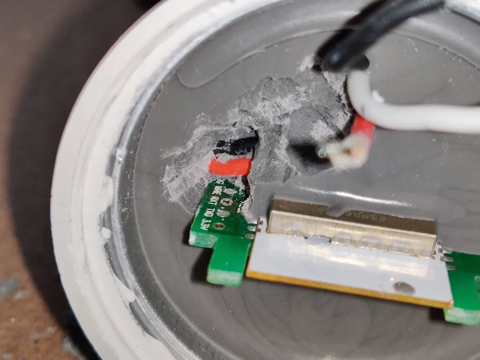
You may get more space by removing the material from the REAR of the board (side without any labels on the pins).
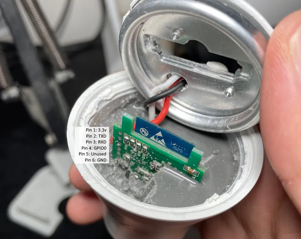
- From the top of the board to the bottom, the 6 pins are:
| PIN | Function |
|---|---|
| 1 | 3.3v |
| 2 | TXD |
| 3 | RXD |
| 4 | GPIO0 |
| 5 | Not used for flashing |
| 6 | GND |
(Thanks to @jakre1 for this info)
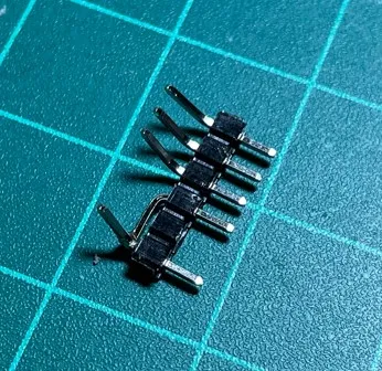
- One way to pull GPIO0 low for flash boot is to short pins 6 and 4 together with a little jig. Also, bend the pins to make it easier to fit your flashing cables in the limited space. Alternatively, the pin on the corner of the ESP module (closest to 3.3v pin) is ground.
- Flash using esptool.py with a 3.3V serial port.