


Available from:
Aliexpress.com
Banggood.com
Install method:
USB to Serial
| GPIO # | Component |
|---|---|
| GPIO00 | None |
| GPIO01 | None |
| GPIO02 | None |
| GPIO03 | None |
| GPIO04 | Output Hi |
| GPIO05 | None |
| GPIO09 | User |
| GPIO10 | User |
| GPIO12 | None |
| GPIO13 | None |
| GPIO14 | None |
| GPIO15 | None |
| GPIO16 | None |
| GPIO17 | None |
| GPIO18 | None |
| GPIO19 | PWM 1 |
| GPIO20 | None |
| GPIO21 | PWM 2 |
| GPIO22 | None |
| GPIO23 | None |
| GPIO24 | None |
| GPIO25 | None |
| GPIO26 | None |
| GPIO27 | None |
| GPIO6 | None |
| GPIO7 | None |
| GPIO8 | None |
| GPIO11 | None |
| GPIO32 | None |
| GPIO33 | None |
| GPIO34 | None |
| GPIO35 | None |
| GPIO36 | None |
| GPIO37 | None |
| GPIO38 | None |
| GPIO39 | None |
{"NAME":"Mijia Desk Lamp 1S (MJGJD02YL)","GPIO":[0,0,0,0,3840,0,1,1,0,0,0,0,0,0,0,416,0,417,0,0,0,0,0,0,0,0,0,0,0,0,0,0,0,0,0,0],"FLAG":0,"BASE":1,"CMND":"DimmerRange 45,255"}tasmota32solo1... binaries.
Hardware
There are three GPIOs in use:
GPIO04: Global light enable/disable. As long as this output is high, the WW/CW channels will light.GPIO19: Cold White channelGPIO21: Warm White channel
Templates
This template keeps GPIO4 high and relies on Tasmota setting both GPIO19 and GPIO21 to fully off to shut the light off.
Most people should use this template.
{"NAME":"Mijia Desk Lamp 1S (MJGJD02YL)","GPIO":[0,0,0,0,3840,0,1,1,0,0,0,0,0,0,0,416,0,417,0,0,0,0,0,0,0,0,0,0,0,0,0,0,0,0,0,0],"FLAG":0,"BASE":1,"CMND":"DimmerRange 45,255"}
If you want to control the global on/off (GPIO04) independently of the WW/CW channels, use this template:
{"NAME":"Mijia Desk Lamp 1S (MJGJD02YL)","GPIO":[0,0,0,0,224,0,1,1,0,0,0,0,0,0,0,416,0,417,0,0,0,0,0,0,0,0,0,0,0,0,0,0,0,0,0,0],"FLAG":0,"BASE":1,"CMND":"DimmerRange 45,255"}
Dimmer Range
In testing, extremely low brightness values for both the WW and CW channel had some undesirable behavior:
- Values lower than ~30 didn’t light at all
- Values between 30-35 caused unpleasant flicker
- Values lower than ~40 would also cause flicker when attempting to light the WW and CW channels together
For this reason, a DimmerRange of 45-255 is suggested. Tasmota will let you dim the light as low as possible without flicker.
Your lamp, eyes and needs will differ so feel free to see if a lower dimmer value will work for you by unlocking the full dimmer range with DimmerRange 0,255 and then playing with the ct and dimmer commands to find the lowest tolerable brightness for your needs.
That is why you see the DimmerRange 45,255 command in the above templates.
Serial Flashing
Please see the Hardware Preparation page for general instructions.
Read the instructions below thoroughly before attempting!
Note: The test pads for programming the chip will require you to remove a plastic cap that is glued on. For best results, use pliers with non-marring grips to prevent/minimize cosmetic damage to the end cap. The cap can be glued back in place after a successful flash with a small drop of superglue or similar.
Note: It is likely that both the WW and CW LEDs will briefly light up during the flashing process. When this happens, you will draw more current than a typical USB <-> Serial adapter can provide. At best you’ll cause a brownout and the flash will be interrupted.
Use a dedicated 5V supply that can provide at least 10W of power while flashing the lamp! Make sure that the GND wire from your serial programmer and the GND wire for your dedicated 5V2A/10W supply are tied together or you will likely destroy some of the electronics on both the lamp, your serial adapter and possibly your computer/USB hub!
The ESP32 chip on this PCB is a single core version.
Follow the instructions for flashing the ESP32 version of Tasmota, specifically the tasmota32solo1 version!
Extracting the PCB
- Remove the lamp bar from the the magnetic mount on top of your monitor.
- Locate the small rectangle shaped protrusion from the lamp tube that mates with the magnetic mount. The protrusion has two small pogo pins on it.
- With the protrusion facing you, locate the plastic cap closest to the product information. This should be plastic cap on the left side of the tube.
- Use pliers or similar to grip the plastic cap.
- Twist the cap to break the glue. Do not twist more than a few degrees! The plastic cap has some features that will come into contact with and could damage the PCB if rotated too far!
- The plastic cap should be loose enough to pull off by hand. Do so without rotating more than necessary!
- You should be greeted with two more pogo pins that interface with a small antenna on the inside of the plastic cap. If you don’t see this, you removed the wrong cap. Set cap aside.
- Use a razor blade or similar to peel back the grip-tape sticker on the protrusion. Underneath the sticker will be two small philips screws. If you’re careful and manage to remove the sticker in one piece you might be able to re-apply it during reassembly. The lamp functions fine without the sticker, though.
- Remove the two small screws that were underneath the sticker. The metal protrusion and small plastic part containing the two pogo pins should come free. Set these aside.
- In good lighting, use a camera or other means to note how both the plastic diffuser and PCB are installed into the aluminum tube.
- Gently remove the clear plastic diffuser from the lamp tube and set aside. The matte finish on the interior side of the diffuser is a fingerprint magnet. Consider using clean gloves for this step.
- Carefully slide the PCB out of the aluminum tube. Be mindful of the two spring like contacts on the back of the PCB that mated with the pogo pins!
Repeat these steps in reverse order to re-assemble the lamp.
Flashing
- Flip the PCB over so the ESP32 and other electronics are facing you.
- The PCB is supported by 4 plastic sleds that are heat-staked onto the PCB. The one sled closest to the ESP32 can be removed for easier access to the
3v3test point. Use flush cutters or similar to carefully cut the plastic back so the ‘sled’ can fall away. Set the sled aside. It can be re-attached with hot glue or similar if desired. - Locate the test points:
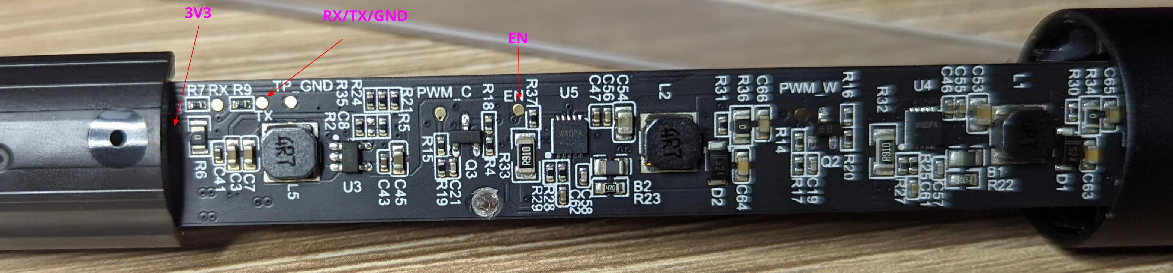
GPIO0. This pin is not marked. It is the test point closest to the ESP32 chip, just off the bottom right corner.TP_GNDENRXTX3V3. This test point is partially obstructed by the plastic sled closest to the ESP chip. If you’re very good with a soldering iron, you can keep the plastic sled in place.
- Solder a jumper wire from the
3V3test point to theENtest point - Solder wires to each of the remaining test points and wire them to your serial programmer board
- Ensure that the wire soldered to the
TP_GNDandGPIO0test point are connected together and wired to theGNDpin on your serial programmer board - Connect the
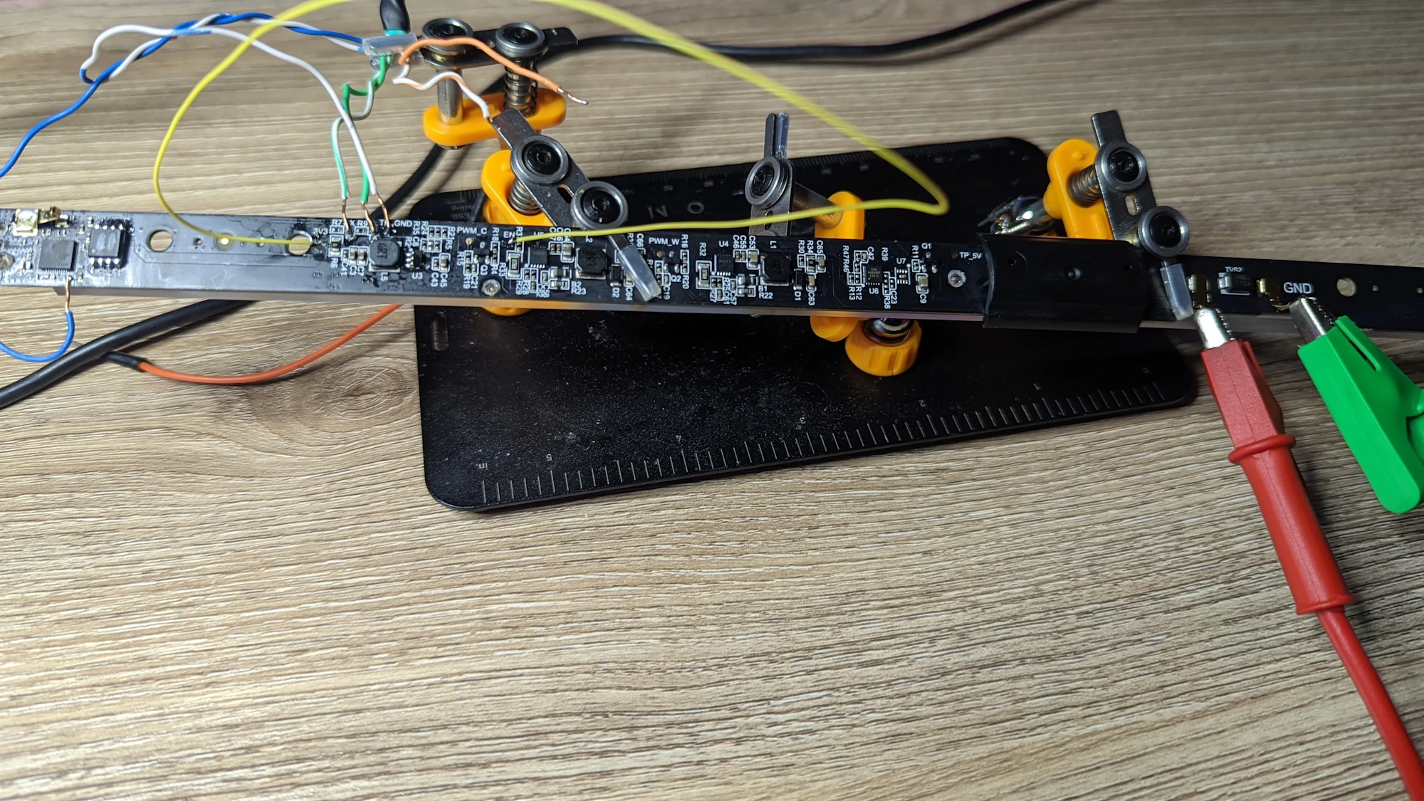
GNDfrom your dedicated 5V power supply to the leaf contact in the middle of the PCB; the contact that mates with the pogo pins. Leads with alligator clips are helpful here! - Connect the positive supply from your dedicated 5V supply to the other leaf spring in the middle of the PCB
- Turn your dedicated 5V supply on
- Begin flashing
After a successful flash, you can turn off the dedicated 5V supply and de-solder all wires and re-assemble or check your work.
Checking your work
- After flashing is complete, remove the supply lead from your dedicated power supply.
- De-solder the wire attached to the unlabeled
GPIO0test point and theENtest point but leave the wires soldered to theRXandTXandTP_GNDin place. - Open a serial terminal to observe Tasmota console out. Use
115200as the baud rate. - Re apply the supply lead to power the board back up. The ESP should begin booting Tasmota.
- Optionally user the serial console to configure Tasmota with WiFi…etc
- Power down, de-solder all wires and clean up any flux residue
- Re-assemble the lamp