Available from:
Aliexpress.com
Install method:
Replace module
| GPIO # | Component |
|---|---|
| GPIO00 | None |
| GPIO01 | None |
| GPIO02 | None |
| GPIO03 | None |
| GPIO04 | None |
| GPIO05 | None |
| GPIO09 | None |
| GPIO10 | None |
| GPIO12 | None |
| GPIO13 | PWM 1 |
| GPIO14 | None |
| GPIO15 | None |
| GPIO16 | None |
| GPIO17 | None |
{"NAME":"KL-LED-WIFI-AC","GPIO":[0,0,0,0,0,0,0,0,0,416,0,0,0,0],"FLAG":0,"BASE":18}
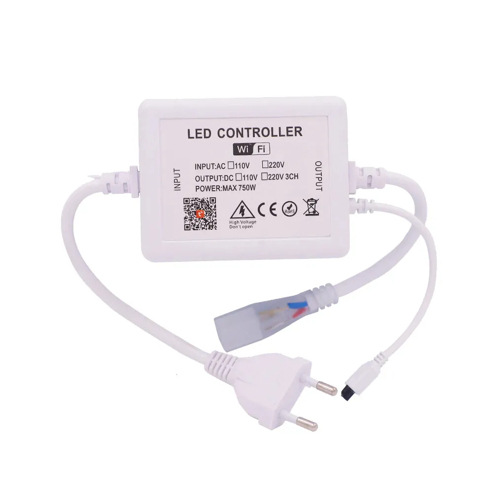
Sold by various dealers on aliexpress - usually “Xunata” branded. Its a high power controller, the output side is AC 110/220V (please be careful!). Its tuya compatible and includes an IR remote controller (GPIO15).
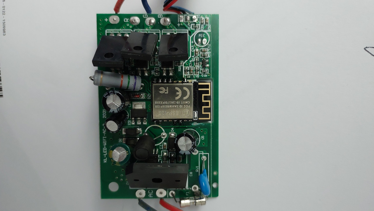
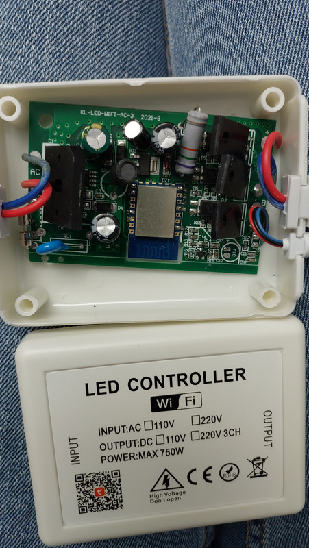
Case can be opened by prying carefully on the sides and corners without damage (its not glued, just very tight fit in the corners - use plastic pick or similar tool). PCB (labeled KL-LED-WIFI-AC-3) contains a unkown chip (advertised as tuya compatible) with no label/markings on silver shield. Bottom of chip reads “XH-006F” which apparently is made by sparkleiot and seems to be a arm cortex M4 variant. This chip needs to be replaced with a ESP12S (or F), which is pin compatible. I didnt use a heat gut here since the PCB is very dense populated and i didnt want to damage things - its possible with just a solder iron and solder wick (takes time…). Once replaced its neccessary to cut a PCB trace since the design pulls GPIO15 up preventing the ESP from boot (this is the IR receiver PIN). I did cut this near the the top right corner, which was easy. (Hint: use kapton tape before soldering and isolate GPIO15).
Once done the PWM for controlling the LED strip is GPIO13 and can be used without problems. The PCB includes a IR receiver - details are unknown - it might be on some of the GPIOs and usable.
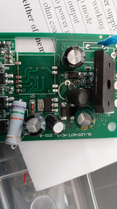
Pictures:
PCB before change:
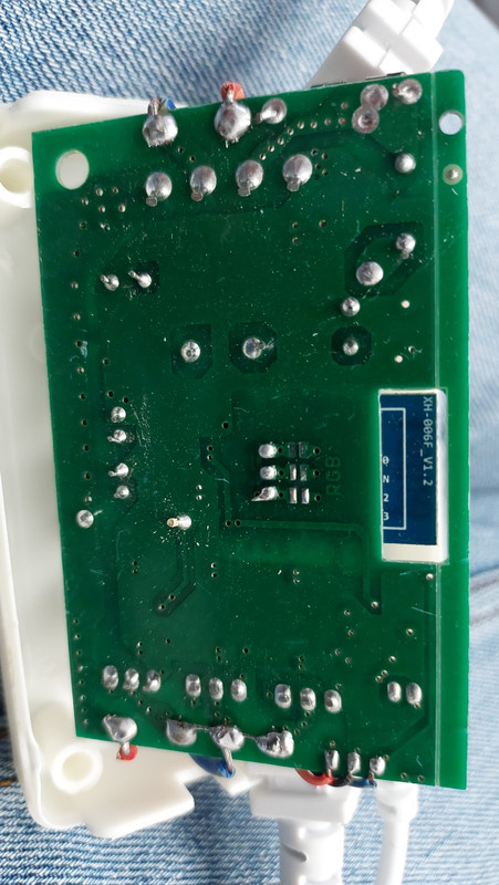
 PCB underside before change:
 PCB without chip:
 PCB with ESP12S and cut trace (near SMD LED from ESP12S):