


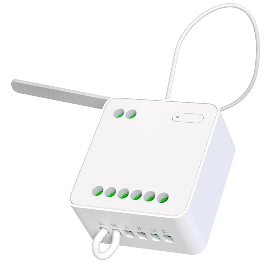
Yeelight Dual Control Switch Module (YLAI002)
Available from:
Alza.de
Aliexpress.com
Install method:
USB to Serial
| GPIO # | Component |
|---|---|
| GPIO00 | None |
| GPIO01 | None |
| GPIO02 | None |
| GPIO03 | None |
| GPIO04 | None |
| GPIO05 | None |
| GPIO09 | None |
| GPIO10 | None |
| GPIO12 | Button_i 1 |
| GPIO13 | None |
| GPIO14 | Relay 1 |
| GPIO15 | None |
| GPIO16 | None |
| GPIO17 | Led_i 1 |
| GPIO18 | Led_i 1 |
| GPIO19 | Switch 1 |
| GPIO20 | None |
| GPIO21 | Switch 1 |
| GPIO22 | None |
| GPIO23 | None |
| GPIO24 | None |
| GPIO25 | None |
| GPIO26 | None |
| GPIO27 | Relay 2 |
| GPIO6 | None |
| GPIO7 | None |
| GPIO8 | None |
| GPIO11 | None |
| GPIO32 | Switch 3 |
| GPIO33 | Switch 4 |
| GPIO34 | None |
| GPIO35 | None |
| GPIO36 | None |
| GPIO37 | None |
| GPIO38 | None |
| GPIO39 | None |
Configuration for ESP32
{"NAME":"YLAI002","GPIO":[0,0,0,0,0,0,0,0,96,0,224,0,0,320,320,160,0,160,0,0,0,0,0,225,0,0,0,0,162,163,0,0,0,0,0,0],"FLAG":0,"BASE":1,"CMND":"SO127 1"}
Flash only with ESP32-SOLO1
tasmota32solo1... binaries.
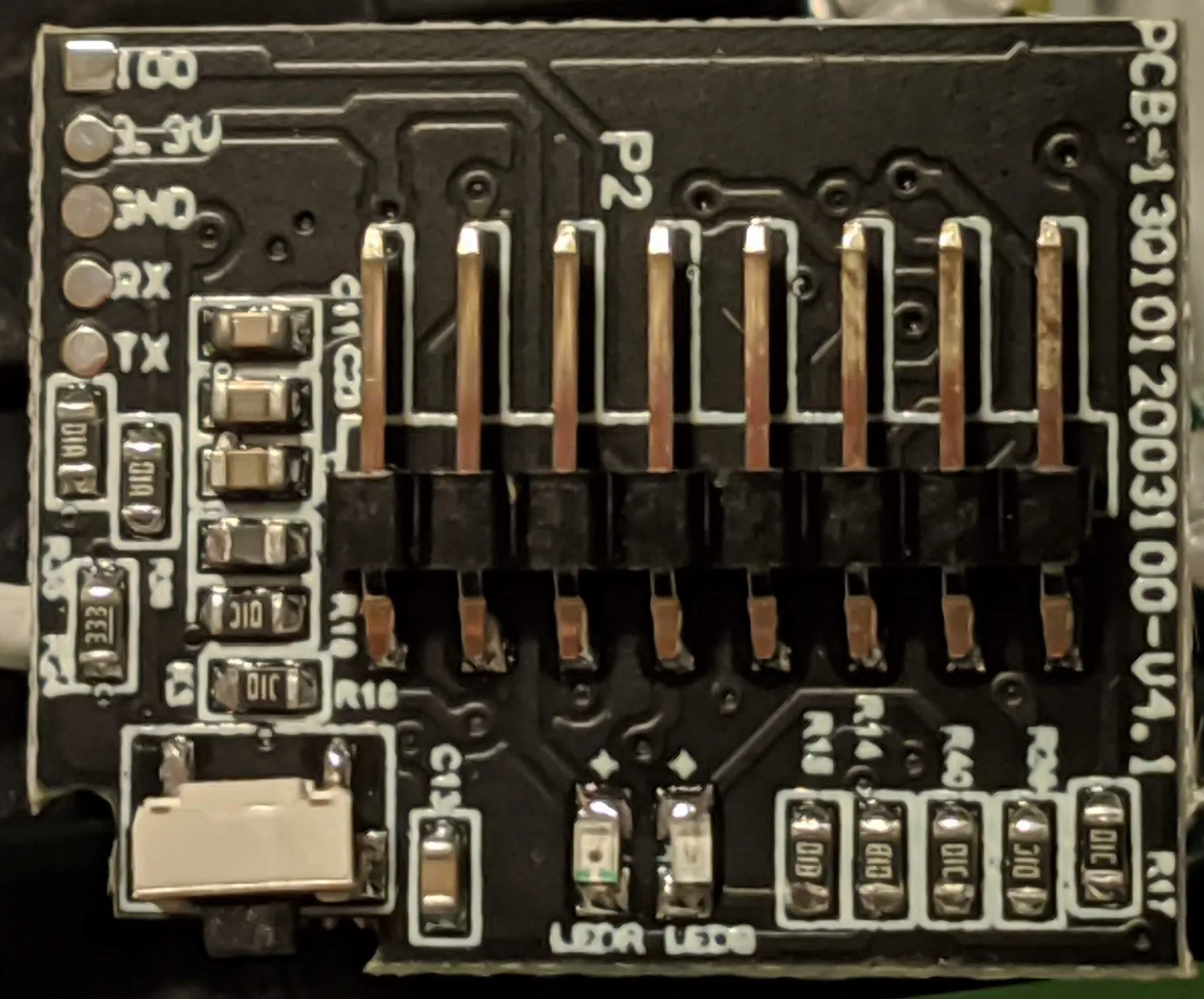
Pry open the lid in the middle and lift the ESP32 module PCB with pliers from the mains PCB.
Serial Flashing
All pins necessary for flashing are labelled on the module PCB.
Pins
| GPIO | Function | Label |
|---|---|---|
| GPIO12 | Button_i | Button (not working) |
| GPIO14 | Relay2 | L2 |
| GPIO17 | Ledi 1 | Blue LED (connection status) |
| GPIO18 | Ledi 2 | Red LED (relay 1 and 2 status) |
| GPIO27 | Relay1 | L1 |
| GPIO19 | Switch2 | S2 |
| GPIO21 | Switch1 | S1 |
| GPIO33 | Switch3 | K2 |
| GPIO32 | Switch4 | K1 (not triggering) |
K1 is not triggering on switch toggles. If you want to show relay status on its respective LED, set any unused GPIO as LedLink.
Unlike the original firmware you can simultaneously use S0, S2 and K2 as 3 switch inputs.