


Available from:
Amazon.com
Install method:
USB to Serial
| GPIO # | Component |
|---|---|
| GPIO00 | None |
| GPIO01 | None |
| GPIO02 | None |
| GPIO03 | None |
| GPIO04 | Led2 |
| GPIO05 | Relay1 |
| GPIO09 | None |
| GPIO10 | None |
| GPIO12 | Led1 |
| GPIO13 | None |
| GPIO14 | Button1 |
| GPIO15 | None |
| GPIO16 | None |
| FLAG | None |
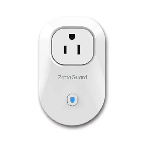
{"NAME":"ZettaGuard S25","GPIO":[0,0,0,0,53,21,0,0,52,0,17,0,0],"FLAG":0,"BASE":18}Very similar to the Orvibo B25.
Simple disassembly, remove the screw cover at the top rear of the plug. Headers are present on the board, use the Ground, TX, RX and GPIO0 pins on the test pads, the “5V” pin marked on the board did not work for me using 3.3v or 5v on any of the plugs that I’ve flashed. Attach 3.3v/Vcc directly to the ESP chip, it is the very top left pin (the side with the relay) with the antenna side of the board facing up.
You may have to maintain shorting GPIO0 to ground for an extended period of time, all of the plugs that I flashed needed GPIO0 shorted to ground for at least 10 seconds to enter programming mode. “