


Available from:
Amazon.co.uk
Manufacturer:
Devola.co.uk
Install method:
USB to Serial
| GPIO # | Component |
|---|---|
| GPIO00 | None |
| GPIO01 | None |
| GPIO02 | None |
| GPIO03 | None |
| GPIO04 | Relay 1 |
| GPIO05 | User |
| GPIO09 | None |
| GPIO10 | None |
| GPIO12 | None |
| GPIO13 | SerBr Tx |
| GPIO14 | None |
| GPIO15 | SerBr Rx |
| GPIO16 | None |
| GPIO17 | None |
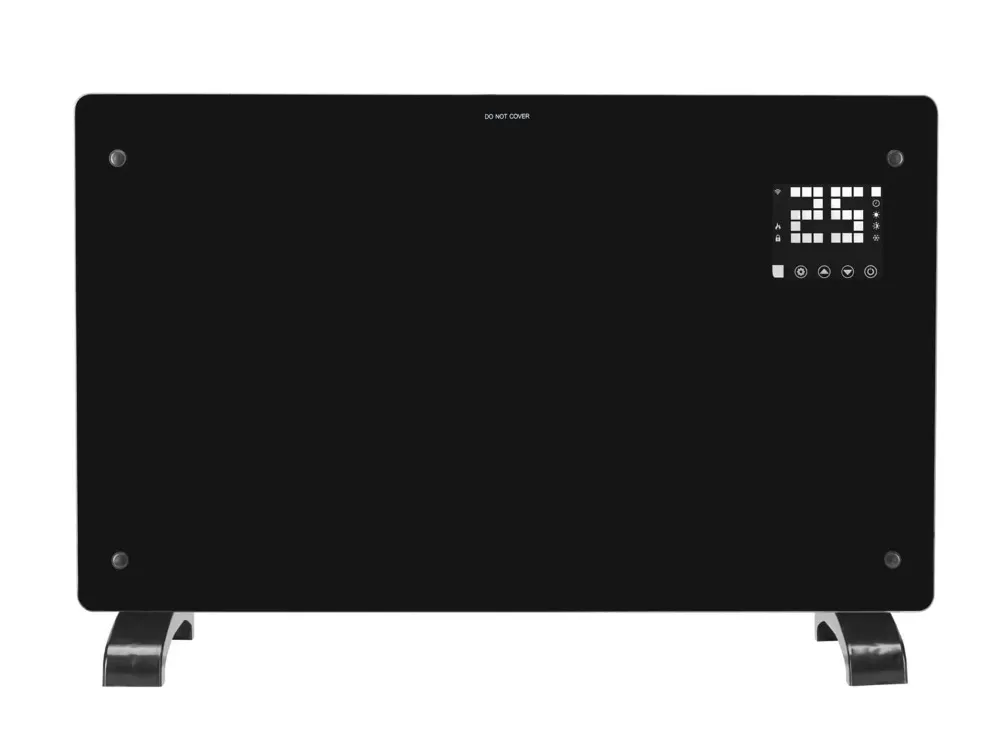
{"NAME":"Devola Heater","GPIO":[0,0,0,0,224,1,0,0,0,1824,0,1792,0,0],"FLAG":0,"BASE":18}This heater comes in a range of form factors and power ratings, but they all seem to work the same way. Physically, the glass-fronted heaters are very similar to the Klarstein ones .
The difference is in the Tuya ESP8266 module used, and the non-standard protocol that’s utilised between the ESP and the MCU.
Flashing is straightforward:
- remove the TYJW2S-5V module that’s similar to the one shown in the Klarstein template
- solder a 6-pin header on to the TXD0 through to 3.3V pins
- connect your FTDI with Rx to TXD0, Tx to RXDO, GND to GND, 3.3V to 3.3V, and hold the BOOT pin to GND while inserting the FTDI adapter. DO NOT USE 5V AS YOU WILL FRY THE CHIP!
- Use Tasmotizer to load the Tasmota firmware
- Don’t reboot the module while attached to the FTDI - it may not successfully boot, and might corrupt the firmware. Instead, reattach it to the heater and reassemble the heater (for safety’s sake, don’t skimp and run the heater with the cover off).
Once you’ve booted and connected to the default 192.168.4.1 access point, set your MQTT server parameters and load the following rules in the console:
RULE1
  ON System#Init do sserialsend5
    f1f10210000000000000000000000000000400167E ENDON
  ON WiFi#Connected do sserialsend5
    f1f10210000000000000000000000000000300157e ENDON
  ON Mqtt#Connected do sserialsend5
    f1f10210000000000000000000000000000100137e ENDON
  ON Mqtt#Disconnected do sserialsend5
    f1f10210000000000000000000000000000300157e ENDON
  ON Wifi#Disconnected do sserialsend5
    f1f10210000000000000000000000000000100137e ENDON
  ON sserialreceived#Data=F2F20600067E DO Wificonfig 2 ENDON
This rule enables intelligent use of the WiFi icon on the panel (it flashes slow on System Init, flashes fast when WiFi connected but no MQTT yet or when MQTT connection is lost, and goes solid on when MQTT connected. Also, when the Power button is held down for 3 seconds, it forces Tasmota to reboot into Access Point mode (as with the stock firmware).
RULE2
  ON Mqtt#Connected DO RuleTimer1 60 ENDON
  ON Rules#Timer=1 DO backlog sserialsend5 f1f10100017e; ruletimer1 60 ENDON
This rule polls the MCU every 60s as a keep-alive which triggers the MCU to send the status hex string via a tele/
tele/tasmota_B7AE5F/RESULT = {""SSerialReceived"":""F2F202100202020019000100010015010000014A7E""}
Deconstructing this status string is a challenge - you may want to take advantage of an MQTT helper app I wrote to transform it into discrete MQTT messages for POWER, CHILDLOCK, MODE, TEMP, TIMER and SETPOINT - see https://github.com/gooman-uk/devola-mqtt
RULE3
  ON Power1#state=1 DO sserialsend5
    F1F10210010002001900000000010001000001317E ENDON
  ON Power1#state=0 DO sserialsend5
    F1F10210020002001900000000010001000001327E ENDON
This rule uses the template’s assignment of dummy GPIO 4 to a Relay to allow simple access to turning the heater on and off through a simple ““cmnd/tasmota/POWER”” message, and also allows toggling it on the Tasmota web page
If you’re planning to build and unpack the hex strings yourself, here’s the structure:
- Bytes 1-2 - Direction - F1F1 from ESP, F2F2 from MCU
- Bytes 2-3 - Padding as far as I can work out - always 02 10
- Byte 5 - Power - 02=OFF, 01=ON
- Byte 6 - Childlock - 02=OFF, 01=ON
- Bytes 7-10 - More padding - always 02 00 19 00
- Byte 11 - Mode - 01=off, 02=low, 03=high, 04=anti-frost
- Byte 12 - Setpoint temperature, converted to hex
- Bytes 13-14 - Timer - 0100 = off, 0001 = on, 0002 = 1 hr, 0003 = 2 hrs (etc)
- Byte 15 - Ambient temperature, converted to hex
- Bytes 16-19 - More padding - always 01 00 00 01
- Byte 20 - Additive checksum of bytes 2-19
- Byte 21 - Terminator - always 7E