


Available from:
Jbhifi.com.au
Install method:
USB to Serial
| GPIO # | Component |
|---|---|
| GPIO00 | None |
| GPIO01 | None |
| GPIO02 | None |
| GPIO03 | None |
| GPIO04 | Button1 |
| GPIO05 | Relay1 |
| GPIO09 | None |
| GPIO10 | None |
| GPIO12 | LedLinki |
| GPIO13 | None |
| GPIO14 | Led1i |
| GPIO15 | None |
| GPIO16 | None |
| FLAG | None |
{"NAME":"Lenovo SE-341AC","GPIO":[0,0,0,0,17,21,0,0,158,0,56,0,0],"FLAG":0,"BASE":18}Extremely similar to the Lenovo SE-341A Plug (ZG38C02793). It may even just be a region specific version.
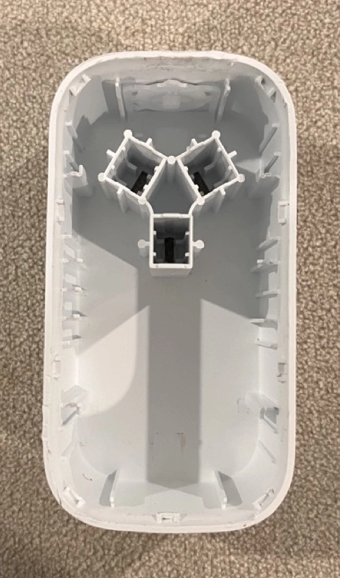
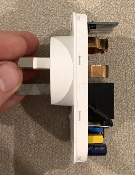
The most difficult part of flashing the firmware is opening the case.
There is one clip on the top, one on the bottom, two on either side, and one in each corner (these are the hardest ones to release) and each clip is only 2mm or so thick.
Here is how I did it:
- I carefully used an X-Acto knife blade to open up the seam on a side
- From there, I inserted a bread knife into the larger gap the X-Acto blade created (as trying to do any prying with the blade could easily snap it) and moved it over to where one of the clips was.
- Once next to the clip, I slightly turned the knife like a screwdriver to pry the case apart a little so that the clip begins to separate from the outer casing.
- When you begin to see a small gap between the clip and the outer casing, block it from going back into its slot by putting another X-Acto blade (be careful if using these, they’re handy because they’re thin and strong, but they are very sharp), or a thin, hard piece of plastic in the way of the clip and it’s slot.
- Repeat this for all the side clips (the top one, the bottom one, the two on the left, and the two on the right).
- Now, using the bread knife, carefully insert it at the top or bottom and wiggle it around to the corner; you should be able to get it into there a bit and use it like a pry bar once in the corner to pop the corner out. This shouldn’t take too much force, you’ll want to get it as close to the corner as possible, and that’s the difficult part.
- Repeat for the other three corners, and you’re in.
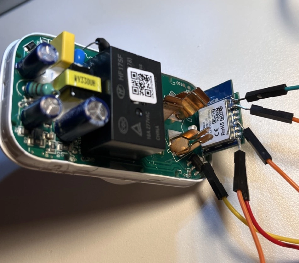
When attaching the leads to the TYWE3S board you might find it’s a tight fit to solder to the 3.3v pad. I used an angled tip but it’s doable with a straight tip. You might even be able to tape it, hot glue it, or hold it by hand (risky, but doable). Just remember it’s a temporary connection and doesn’t have to be strong. It only takes a few seconds to flash.
As usual when flashing the TYWE3S you’ll need to short GPIO0 to GND to enable flashing.
More pictures are available here.
Pinout
 .
.