Available from:
Aliexpress.com
Install method:
USB to Serial
| GPIO # | Component |
|---|---|
| GPIO00 | None |
| GPIO01 | None |
| GPIO02 | None |
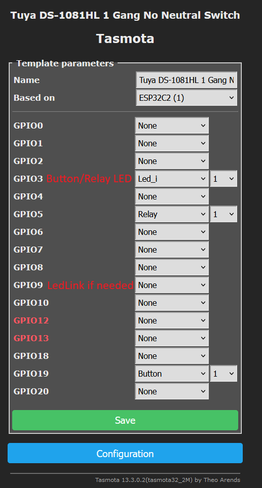
| GPIO03 | Led_i 1 |
| GPIO04 | None |
| GPIO05 | Relay 1 |
| GPIO06 | None |
| GPIO07 | None |
| GPIO08 | None |
| GPIO09 | None |
| GPIO10 | None |
| GPIO11 | None |
| GPIO12 | None |
| GPIO13 | None |
| GPIO14 | None |
| GPIO15 | None |
| GPIO16 | None |
| GPIO17 | None |
| GPIO18 | None |
| GPIO19 | Button 1 |
| GPIO20 | None |
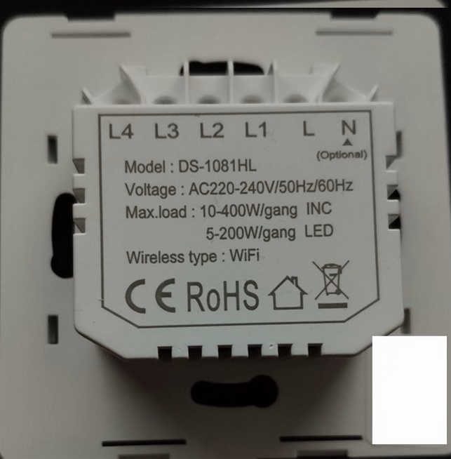
{"NAME":"Tuya DS-1081HL","GPIO":[0,0,0,320,0,224,0,0,0,0,0,0,0,0,0,0,0,0,0,32,0],"FLAG":0,"BASE":1}This light switch is sadly not the same as Tuya T1 DS-1081WL. This one is labeled as DS-1081HL.
PCB
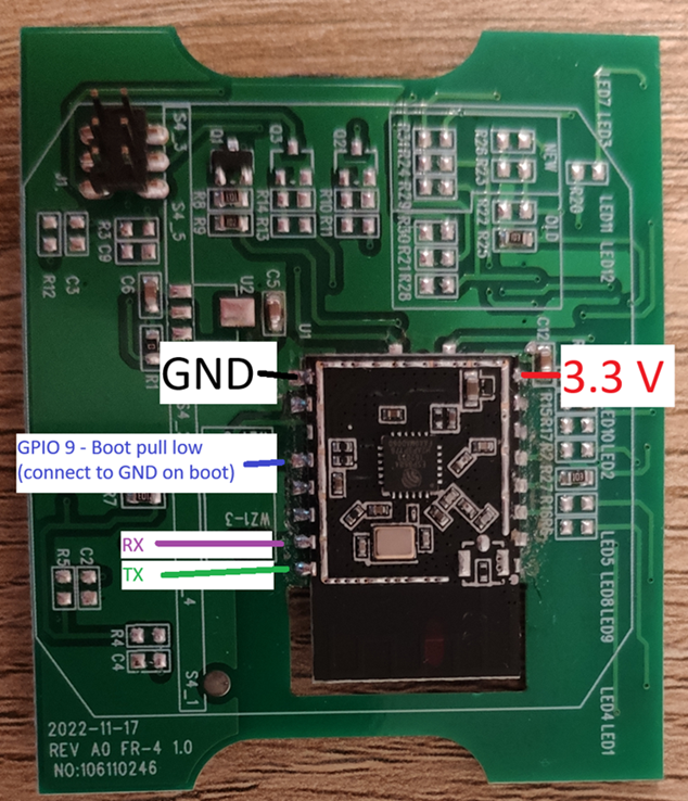
Here is the PCB Pinout and Pins to connect for flashing. GPIO 9 is mandatory to pull to GND when booting to enter flash mode. See also already existing template for ESPC2-12 (GPIO8 is not needed on this PCB). And yes two pins aren’t connected on the ESP Chip. The one above GPIO9 is not connected. Also the EN Pin (right bottom corner) is not connected.

Flashing Firmware
This ESPC2-12 (aka ESP8684) only has 2 MB of flash.
This means you will need a Tasmota firmware which fits in the 2 MB flash. Either compile it yourself or search on google for tasmota specials version 2m (I don’t know if I’m allowed to post links to custom builds). Then flash with esp-tool or similar tools.
.\esptool.exe write_flash 0x0 tasmota32c2_2M.factory.bin
Template and Config
After flashing remove wires and connect PCB back to the main PCB. In my case I couldn’t boot the PCB with only USB power.
Here is the modified template to make the basic functions work. I disabled the LedLink LED because with that, one blue LED would be always on. It can be enabled again when GPIO9 is set as LedLink. Setting GPIO3 as Led_i activates the red LED when the relay / switch is off and switches to an blue led (red led off then) when relay / switch is on.

Back of Case


