


Available from:
Aliexpress.com
Install method:
Replace module
| GPIO # | Component |
|---|---|
| GPIO00 | None |
| GPIO01 | Tuya Tx |
| GPIO02 | None |
| GPIO03 | Tuya Rx |
| GPIO04 | None |
| GPIO05 | None |
| GPIO09 | None |
| GPIO10 | None |
| GPIO12 | None |
| GPIO13 | None |
| GPIO14 | None |
| GPIO15 | None |
| GPIO16 | None |
| GPIO17 | None |
{"NAME":"WL5","GPIO":[0,2272,0,2304,0,0,0,0,0,0,0,0,0,0],"FLAG":0,"BASE":54,"CMND":"DimmerRange 100,1024 | TuyaMCU 11,20 | TuyaMCU 26,21 | TuyaMCU 21,23 | TuyaMCU 24,24 | TuyaMCU 81,26 | TuyaMCU 98,101"}
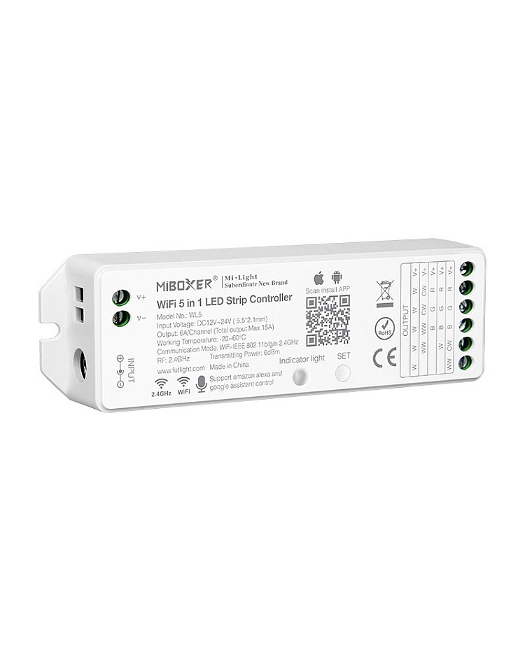
Hardware
The chip used on this board is a WR3 or a WBR3, and requires a transplant. It cannot be flashed. The daughterboard for the SoC is compatible with the ESP12-S. Other formats may be compatible, but may require jumper wires.


The TuyaMCU on board requires the following settings for an RGB strip.
Backlog DimmerRange 100,1024; TuyaMCU 11,20; TuyaMCU 26,21; TuyaMCU 21,23; TuyaMCU 24,24; TuyaMCU 81,26; TuyaMCU 98,101;
Serial Flashing
Please see the Hardware Preparation page for general instructions.
Wiring
Make sure to press the switch and select the mode corresponding to the strip you are using. ie. To use an RGB strip, you press the switch until it flashes red. The setting will stick between restarts. The mode cannot be changed from Tasmota as there are no connection between it and the switch. You can solder a wire from a free GPIO to the switch and change the mode by pulsing the GPIO from Tasmota.
| Light Color | Mode |
|---|---|
| White Flashing | Single Color Mode |
| Yellow Flashing | Dual White Mode |
| Red Flashing | RGB Mode |
| Green Flashing | RGBW Mode |
| Blue Flashing | RGB+CCT Mode |
