Available from:
Pollin.de
Manufacturer:
Chilitec.de
Install method:
Replace module
| GPIO # | Component |
|---|---|
| GPIO00 | User |
| GPIO01 | None |
| GPIO02 | Relay 1 |
| GPIO03 | Relay 2 |
| GPIO04 | User |
| GPIO05 | Led_i 1 |
| GPIO09 | None |
| GPIO10 | None |
| GPIO12 | Button 1 |
| GPIO13 | Button 2 |
| GPIO14 | Button 3 |
| GPIO15 | Relay 3 |
| GPIO16 | None |
| GPIO17 | None |
{"NAME":"MILOS Jalousie","GPIO":[1,0,224,225,1,320,0,0,32,33,34,226,0,0],"FLAG":0,"BASE":18}
Requires configuring shutter support.
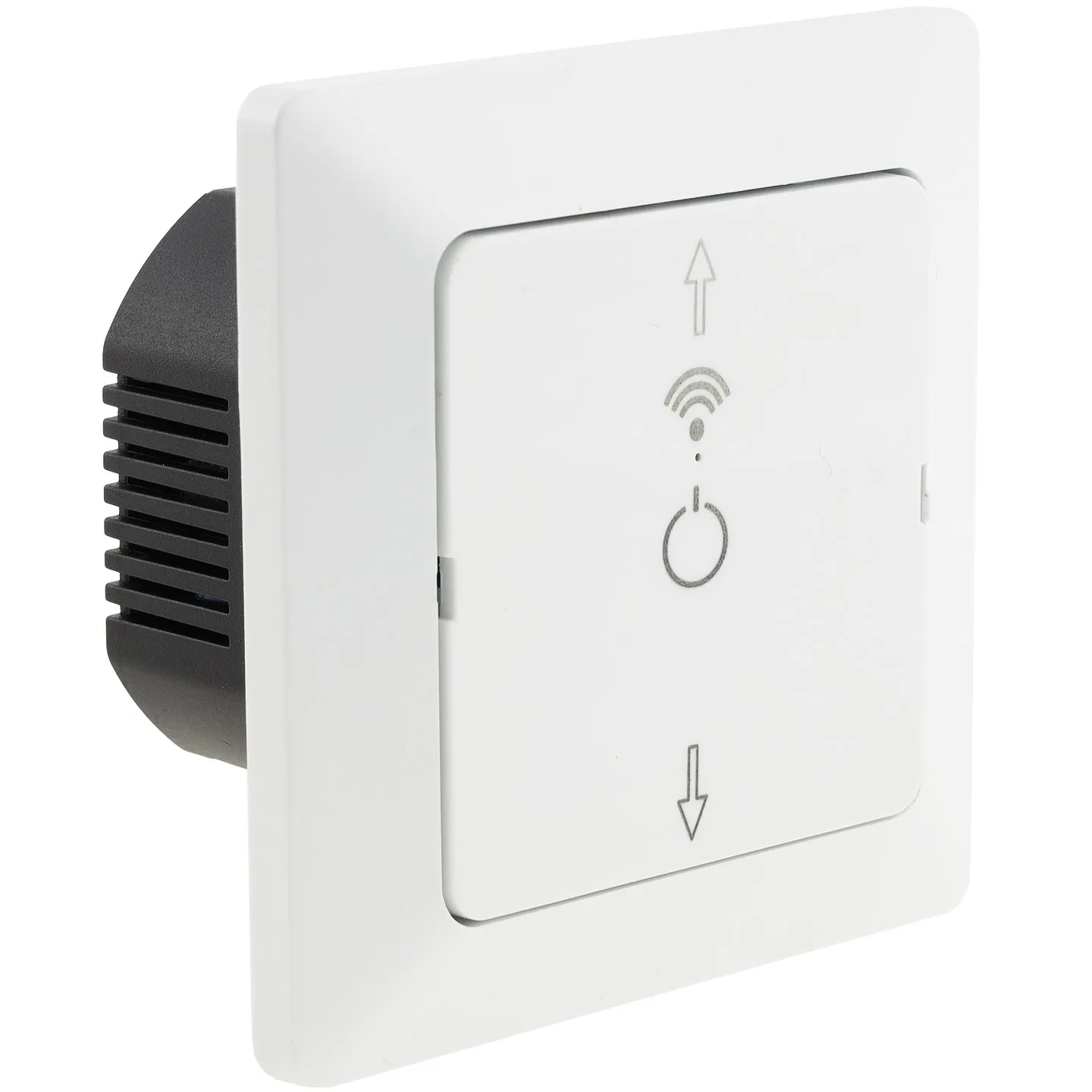
Originally has a RTL based WR3E Module, changing it to a ESP-12S does the trick, no other changes, except maybe you want to populate the two other LEDs but it’s not necessary. Bad circuit: opening the plate will expose contacts with live mains! Some emit a high tone when a relay is active. Front button plate is 55x55mm and will fit e.g. in German standard switch plates, although the matte optics may not fit to the rest.
Real Pinout:
- 0- LED3/R18, not populated
- 1- NC
- 2- NC
- 3- Relay for contact marked L2
- 4- LED2/R17, not populated
- 5- LED1, a blue one visible through a hole
- 12- S2, the center “On” button
- 13- S1, the “Up” button, PCB marking “open symbol”
- 14- S3, the “Down” button, PCB-marking “close symbol”
- 15- Relay for contact L1
- 16- NC
- 17- NC
I’ve set the template so that there is a dummy relay on GPIO2, so the LED can be Link and another function switched with the center button. I use it to switch Automatic and Manual mode, hence the WebButton rename command. L1 is connected to motor “down”, L2 is “up”.
Additional setup:
SO80 1; SO1 0; PowerOnState 0; WebButton 1 Auto; ShutterRelay1 2; Interlock on; Interlock 2,3; ShutterMode 1; ShutterButton1 2 up; ShutterButton1 3 down
I’ve some used without MQTT in standalone Timer mode, the center button then is used to disable timers. To do this I added a simple rule
rule1 on system#boot do backlog power1 1; timers 1 endon on Power1#state do timers %value% endon
this switches the timers on when power is applied, and they follow the Power1 state.


